background image

18

105635

Tool Disassembly

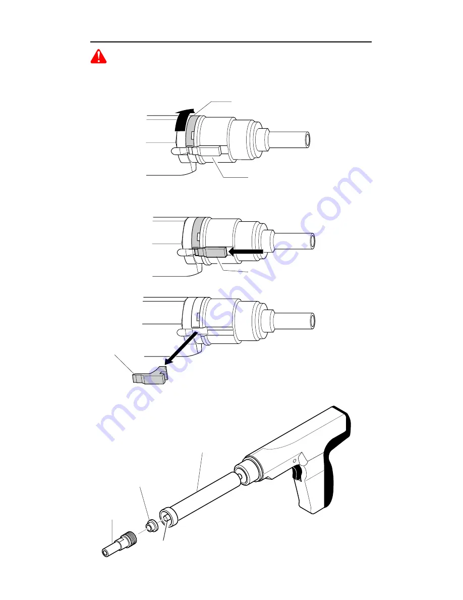
Figure 2 - Removing Stop

Stop

A. REMOVING BARREL ASSEMBLY
1. Using screwdriver, lift end of annular spring and rotate spring until stop is

uncovered (see Figure 1).

Annular Spring

WARNING:  Always unload a powder actuated tool before disassembling,
replacing barrel, cleaning, or assembling.

Stop

3. Pull barrel assembly out of housing.
4. Unscrew muzzle cap.
5. Pull buffer out of muzzle cap (see Figure 3).

Figure 3 - Separating Barrel Assembly from Housing

Stop

Muzzle Cap

Buffer

Barrel

Piston

Figure 1 - Rotating Annular Spring to Uncover Stop

2. Push stop towards rear of tool and remove (see Figure 2).

Summary of Contents for 496

Page 1: ...tool This manual should always accompany the tool and be transferred with it upon change of ownership Operating Instructions POWDERACTUATEDTOOL MANUFACTURERS INSTITUTEINC G 029 A N I N DEPENDENT LABOR A T O R Y T E S T I NG FOR PUBLIC SA F E T Y G 028 Power Pro Semi automatic Model 496 482 1 ...

Page 2: ...ver Power Fastener Recommended Approved Goggles Muzzle Guide Barrel Assembly Trigger Maximum 3 Spall Shield REMINGTON Power Pro Semi automatic Model 496 The Remington Power Pro Model 496 is designed for use with Remington 27 caliber power load strips and Remington power fasten ers which are no longer than 3 Remington power fasteners are manufactured from special steel and heat treated to produce a...

Page 3: ... regulations of many states require that the operator of this tool on a job site be thoroughly trained and certified for competence prior tooperatingthistool Forcertificationprocedures call DESAToolDivision 1 800 626 2237 USA or 1 905 826 8010 Canada 1 Always handle the tool as if it were loaded Before starting work check that the tool is unloaded and the muzzle is clear Never load a tool unless i...

Page 4: ...es and post appropriate warning signs on job sites G 018 G 018 1 Never place your hand over the muzzle Accidental discharge can cause serious injury HANDLING THE TOOL 2 Never place your finger on the trigger until the tool s muzzle is against the work surface 5 Make sure the work area is clean from loose material and debris ...

Page 5: ...tuated tool and power load strips in a locked container Unload tool before storing Keep power loads of different power levels in separate containers 5 If the tool is dropped inspect for damage and repair it before continuing to work Never use a damaged tool 6 Always take precaution to maintain your balance while operating a powder actuated tool POWER LOADS POWE LOAD ...

Page 6: ...t is performed by using a hammer to test drive the particular power fastener to be used into the material If the point penetrates easily the material is too soft If the point becomes blunt the material is too hard If the material fractures cracks or shatters the material is too brittle Test fastenings can be made if the material shows a clear fastener impression and the fastener point is not blunt...

Page 7: ...ne brick or hardened steel Materials of this type tend to shatter and create hazard from flying particles 4 Never drive power fasteners into thin or easily penetrated materials unless it is backed by concrete or steel When in doubt such as when base material is concealed conduct a Center Punch Test See page 6 Check continually to avoid fastening into unsuitable material especially in older buildin...

Page 8: ... into concrete less than three times as thick as the intended fastener penetration within 3 of the edge within 3 of another power fastener or within 3 of a failed power fastener 3 3X 1X 482 38 8 When fastening into masonry walls always drive into horizontal mortar joints never into vertical mortar joints Be careful A poorly laid joint may permit too much penetration and or unsatisfactory holding p...

Page 9: ...work surface and pull the trigger If the tool still fails to fire hold the tool firmly against the work surface for another 30 seconds before advancing the power load strip Use remaining loads in strip Discard power load strip into water or oil WATER 3 Always use the spall shield when driving directly into concrete or steel Always wear goggles 4 Never use a powder actuated tool in an explosive or ...

Page 10: ...ghest power level Always start with the lowest power level green level 3 and increase until a proper fastening is made See page 13 Selecting Power Fasteners and Power Loads IMPORTANT Purple level 6 power load strips will not function in model 496 tool 27 Start YELLOW POWER LEVEL 4 GREEN POWER LEVEL 3 RED POWER LEVEL 5 G 018 G 018 G 018 3 Never use power loads in firearms 5 A color blind person mus...

Page 11: ... the power load strip before removing the power fastener 8 Never pry a power load out of the strip Prying can discharge the load causing serious injury See Troubleshooting Guide page 24 Never attempt to reload used strips G 018 7 Never use common nails or other materials as fasteners Remington Power Fasteners are manufactured from special steel and heat treated to produce a very hard yet ductile f...

Page 12: ...er fastener point protrude through the concrete NOTE Concrete needs to cure for 28 days before maximum fastening holding power will be achieved WHY A POWER FASTENER HOLDS IN STEEL Holding power in steel depends on the elasticity of the steel The steel pushes back on the shank of the power fastener Drop a marble into water the water parts the marble continues down the water closes back This is simi...

Page 13: ...power level green level 3 If the first test fastener does not penetrate to the desired depth move to the next highest power level yellow level 4 Increase until a proper fastening is made IMPORTANT Damage to the tool will result if the above instructions are not followed see illustrations to right and lower right OVERDRIVEN POWER FASTENERS AND PISTON An overdriven power fastener results when too st...

Page 14: ...nst work surface until sliding action of barrel stops 3 Select the proper power level of power load strips Always insert power load strips through bottom of handle Push power load strip in until even with bottom of handle NOTE Failure to start with the lowest power level can result in overdrive condition and will result in damage to tool See page 13 482 70 482 71 2 Insert power fastener into muzzl...

Page 15: ...ll the trigger If the tool still fails to fire hold the tool firmly against the work surface for another 30 seconds before advancing the power load strip Use remaining loads in strip Discard power load strip into water or oil WATER 6 Grasp muzzle cap and slide barrel forward rapidly until it stops Push barrel assembly back into tool to the closed position This advances the power load strip and res...

Page 16: ...7 Firing Pin Guide 1 15 301047 Spring 1 16 501319 Sear 1 17 501320 Spring 1 18 501321 Safety Spring 1 19 501422 Rear Pad 1 20 501423 Bolt 2 21 301531 Advance Spring 1 22 301533 Trigger 1 23 501526 Trigger Pin 1 24 502600 Rocker Arm Assembly Includes Rocker Arm Rocker Arm Pin and Rocker Arm Holder 1 25 501733 Rocker Arm Spring 1 26 501700 Handle Pad Assembly 1 27 501500 Advance Assembly Holder Bar ...

Page 17: ...rel assembly with the wire brush provided with tool Notice Do not attempt to clean power load strip channel with wire brush Apply good quality penetrating lubricant spray such as WD 40 sparingly and wipe dry 1 3 2 4 5 6 7 4 8 9 10 11 12 13 14 15 16 17 18 19 20 21 22 23 24 25 27 26 Parts List 496 ...

Page 18: ...NING Always unload a powder actuated tool before disassembling replacing barrel cleaning or assembling Stop 3 Pull barrel assembly out of housing 4 Unscrew muzzle cap 5 Pull buffer out of muzzle cap see Figure 3 Figure 3 Separating Barrel Assembly from Housing Stop Muzzle Cap Buffer Barrel Piston Figure 1 Rotating Annular Spring to Uncover Stop 2 Push stop towards rear of tool and remove see Figur...

Page 19: ...emoving Handle Pad Assembly and Rear Pad Screws Figure 4 Removing Piston Assembly from Barrel Rear Pad Continued Piston Assembly Handle Pad Assembly Figure 6 Removing Rocker Arm Assembly from Housing Figure 7 Removing Rocker Arm Spring from Handle Pad Rocker Arm Spring Assembly Handle Pad Rocker Arm Assembly Barrel C REMOVING ROCKER ARM ASSEMBLY 1 Rocker arm assembly is located in housing Pull roc...

Page 20: ...h Pin Figure 11 Removing Outer Liner Assembly from Housing Ball Bearing F REMOVING OUTER LINER ASSEMBLY FROM HOUSING 1 Grasp outer liner assembly and remove from housing 2 Remove spring and ball bearing located at rear of liner Trigger Pin Figure 10 Removing Trigger Pin and Trigger Assembly E REMOVING TRIGGER ASSEMBLY 1 Remove trigger pin from housing with hammer and punch see Figure 10 2 Remove t...

Page 21: ... assembly in outer liner assembly 3 Insert spring and sear through slot on outer liner assembly and into slot in firing pin assembly see Figure 12 4 Slide firing pin guide on outer liner assembly see Figure 13 5 Slide springs on outer liner assembly see Figure 13 D REPLACING ROCKER ARM ASSEMBLY 1 Insert rocker arm spring in recess on assembly handle pad see Figure 14 2 Put rocker arm assembly insi...

Page 22: ...on Figure 18 Inserting Barrel Assembly into Outer Liner Assembly Outer Liner Assembly E ATTACHING REAR PAD AND HANDLE PAD ASSEMBLY 1 Replace the handle pad assembly Tighten screw with 3mm Allen wrench 2 Replace the rear pad with two screws provided The screws will also secure the outer liner replaced in step A Inserting Outer Liner Assembly into Housing see Figure 16 Figure 16 Replacing Handle Pad...

Page 23: ...op Figure 19 Replacing Stop Outer Liner Assembly 6 Push stop towards front of tool see Figure 20 Stop Figure 20 Pushing Stop towards Front of Tool Annular Spring Stop Figure 21 Rotating Annular Spring to Secure Stop 7 Rotate annular spring until stop is covered see Figure 21 ...

Page 24: ...elow Remove barrel assembly see pages 18 20 Replace alldamagedormissingparts Replace piston or piston ring or take tool to your distributor Change either to next lower power load or next longer length fastener Remove barrel assembly see pages 18 20 Replace other parts if damaged Replace advance bar or springs Clean tool Notice Do not attempt to clean power load strip channel with wire brush You ma...

Page 25: ...0 E Valparaiso IN 46383 9704 219 462 7441 1 800 362 6951 F B D 1349 Adams Street Bowling Green KY 42103 3414 270 846 1199 1 800 654 8534 ROBI TOOL SALES 160 Broadway Somerville MA 02145 0002 617 776 1234 FOUR FLAGS POWER PRODUCTS 1115 Stateline Road Niles MI 49120 4728 616 684 2697 Parts Department 1 800 268 4983 MASTER PARTS DIST 1184 Wilson Ave NW Grand Rapids MI 49544 3458 US 1 800 446 1446 616...

Page 26: ...w Yellow Yellow Red 1 4 Plywood or Pegboard 1 1 1 Concrete Cement Block Steel 3 16 to 3 8 Thick Yellow Green Yellow Red Concrete Cement Block 1 1 Yellow Green Power load listings are recommendations only If you are in doubt try a test fastening using the next lightest power load Load Color Code Level Load Case Number Strength Body Head 3 medium brass Green 4 heavy brass Yellow 5 extra heavy brass ...

Page 27: ...27 105635 Maintenance Log Date Maintenance Performed ...

Page 28: ...prices This expressed and limited warranty is the only warranty on this product and to the full extent permitted by law There are no other warranties expressed or implied including warranties of merchantability and or fitness for a particular purpose which extend beyond the terms of this expressed and limited warranty To the full extent permitted by law the liability of DESA for personal injury pr...

Reviews: