

2.
ceiling temperature. The subsequent operation of the sol-
der link opens the waterway and causes the deflector to
drop into position to distribute the discharging water in a
hemispherical pattern below the sprinkler deflector. Any
adjustment of thread engagement between the cover
plate and cup will assure that the drop-down deflector is
properly located below the ceiling. The residential distri-
bution pattern contains a finer droplet size than a standard
sprinkler, and the pattern produces significantly higher
wall wetting.
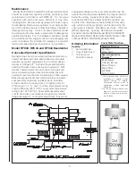
After a 2
5
/
8
inch diameter hole is cut in the ceiling, the
sprinkler is to be installed with the Model FC Wrench.
When installing a sprinkler, the wrench is first positioned
into the sprinkler/cup assembly and around the hexagonal
body of the sprinkler frame. The Wrench must bottom out
against the cup in order to ensure proper, safe installation.
The sprinkler is then tightened into the pipe fitting. When
inserting or removing the wrench from the sprinkler/cup
assembly, care should be taken to prevent damage to
the sprinkler. DO NOT WRENCH ON ANY OTHER PART
OF THE SPRINKLER/CUP ASSEMBLY. MODEL RFC30,
RFC43 AND RFC49 CONCEALED SPRINKLERS MUST
BE INSTALLED ONLY WITH 135°F RATED COVERS.
Note:
A leak tight ½” NPT (R1/2) sprinkler joint can be ob-
tained with a torque of 8-18 ft-lbs (10,8 - 24,4 N-m). Do not
tighten sprinklers over maximum recommended torque. It
may cause leakage or impairment of the sprinklers.
Cover assemblies provide up to
1
/
2
” (13mm) of adjust-
ment. Turn the cover clockwise until the flange is in con-
tact with the ceiling. For the push-on/thread-off option, the
cover assembly is pushed onto the cup and final adjust-
ment is made by turning the cover clockwise until the skirt
flange makes full contact with the ceiling. Cover removal
requires turning in the counter-clockwise direction.
In ceilings that have a plenum space above the sprinkler,
the plenum space may have neutral or negative pressur-
ization but must not be positively pressurized. Inspect all
sprinklers after installation to ensure that the gap between
the cover plate and ceiling and the 4 slots in the cup are
all open and free from any air flow impediment.
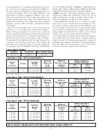
Temperature Rating
Sprinkler
Cover Plate
Max. Ambient Temp.
165°F/74°C
135°F/57°C
100°F/38°C
Installation Data: RFC30 (SIN RA0611)
Thread
Size
inch (mm)
K Factor
Sprinkler
Spacing
ft. (m)
Maximum
Distance to
Wall
ft. (m)
Minimum
Distance between
sprinklers
ft. (m)
Minimum Required
Sprinkler Discharge
Flow
gpm (Lpm)
Press.
psi (bar)
½” (15mm)
½” (15mm)
3.0
3.0
12 x 12 (3.6x3.6)
14 x 14 (4.3x4.3)
6 (1.83)
7 (2.13)
8 (2.43)
8 (2.43)
9 (34.1)
10 (37.8)
9.0 (0.62)
11 (0.76)
Note: 1 bar = 100 Kpa
Installation Data: RFC43 (SIN RA0612)
Thread
Size
inch (mm)
K Factor
Sprinkler
Spacing
ft. (m)
Maximum
Distance to
Wall
ft. (m)
Minimum
Distance between
sprinklers
ft. (m)
Minimum Required
Sprinkler Discharge
Flow
gpm (Lpm)
Press.
psi (bar)
½” (15mm)
½” (15mm)
½” (15mm)
½” (15mm)
½” (15mm)
4.3
4.3
4.3
4.3
4.3
12 x 12 (3.6x3.6)
14 x 14 (4.3x4.3)
16 x 16 (4.9x4.9)
18 x 18 (5.5x5.5)
20 x 20 (6.0x6.0)
6 (1.83)
7 (2.13)
8 (2.43)
9 (2.74)
10 (3.05)
8 (2.43)
8 (2.43)
8 (2.43)
8 (2.43)
8 (2.43)
12 (45)
13 (49)
13 (49)
18 (68)
21 (79)
7.8 (0.54)
9.1 (0.63)
9.1 (0.63)
17.5 (1.21)
23.8 (1.64)
Note: 1 bar = 100 Kpa
Installation Data: RFC49 (RA0616)
Thread
Size
inch (mm)
K Factor
Sprinkler
Spacing
ft. (m)
Maximum
Distance to
Wall
ft. (m)
Minimum
Distance between
sprinklers
ft. (m)
Minimum Required
Sprinkler Discharge
Flow
gpm (Lpm)
Press.
psi (bar)
½” (15mm)
½” (15mm)
½” (15mm)
½” (15mm)
½” (15mm)
4.9
4.9
4.9
4.9
4.9
12 x 12 (3.6x3.6)
14 x 14 (4.3x4.3)
16 x 16 (4.9x4.9)
18 x 18 (5.5x5.5)
20 x 20 (6.0x6.0)
6 (1.83)
7 (2.13)
8 (2.43)
9 (2.74)
10 (3.05)
8 (2.43)
8 (2.43)
8 (2.43)
8 (2.43)
8 (2.43)
13 (49)
13 (49)
13 (49)
17 (64.3)
20 (75.7)
7.0 (0.48)
7.0 (0.48)
7.0 (0.48)
12.0 (0.83)
16.7 (1.14)
Note: 1 bar = 100 Kpa
FOR SLOPED CEILING APPLICATIONS SEE RASCO BULLETIN 035.


