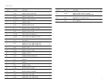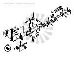
KEY NO.
1
2
3
4
5
6
7
8
9
10
11
12
13
14
15
16
17
18
19
20
21
22
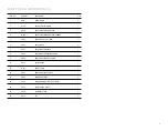
KEY NO.
23
24
25
26
27
PART NO.
703
704
705-2
707
708
709
710
M711
M712
718
D720
725
725-7
M726
727
728
M729
M732
M734
741
N746
C749
PART NO.
H777
412-1
154
110-1
402
Q’TY
1
2
1
1
1
2
1
1
1
1
2
1
1
1
1
1
1
1
1
1
1
1
Q’TY
1
1
7
1
1
PART NAME
ZIG ZAG CAM & GEAR (ASSEMBLY)
SET SCREW (3) FOR NO. 703, 707
NEEDLE DISPLACEMENT REGULATOR (ASSEMBLY)
SHAFT FOR NO 705-2
ZIG ZAG WIDTH REGULATOR
ZIG ZAG WIDTH REGULATOR PIN (2) FOR NO. 708, M712
SET SCREW FOR NO 708(1)
ZIG ZAG CONNECTING PLATE
ZIG ZAG REGULATING LEVER
SPRING WASHER FOR NO. 709
ZIG ZAG WIDTH LEVER KNOB (2)
ZIG ZAG CONNECTING LINK SLIDE BLOCK (ASSEMBLY)
COLLAR FOR NO. 725
ZIG ZAG VERTICAL SHAFT
SNAP RING FOR NO. M726 (1)
ZIG ZAG VERTICAL SHAFT ARM
NEEDLE POSITION COMPLETE LEVER
CLICK STOPPER FOR NO. M729
NEEDLE POSITION COMPLETE LEVER GUIDE
SNAP RING (2) FOR NO. 707
SPRING FOR NO. M711
ZIG ZAG REGULATING LEVER PIN
PART NAME
ZIG ZAG CONTROL PLATE
SET SCREW FOR NO. 725(1)
SET SCREW FOR NO. M711(2), M729(1), M732(1), N747(1),
H777(2)
SET SCREW FOR NO. M732(1)
SET SCREW FOR NO. 728(1 )
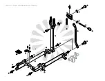
GROUP 7
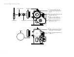
TO REGULATE THE WIDTH OF ZIGZAG STITCH
Moving the zigzag width lever to the desire zigzag width as marked on the panel accord-
ingly can regulate the zigzag width. For instance, “0” as straight while “5” will be the
maximum zigzag width
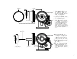
NEEDLE POSITION SELECTION
With the zigzag width lever set at “0” and the needle position selector move to “L”, a
straight line stitches will be sewn at the left side of the needle hole.
With the zigzag width lever set at “0” and the needle position selector move to “C” or
“R”, a straight line stitches will be sewn at the middle or the right of the needle hole.
As adjusting of zigzag width with the needle position selection as mentioned above, a
variety of ornamental stitches can be sewn.
L
C
R
24
Summary of Contents for BARRACUDA 200ZW
Page 1: ...INSTRUCTION MANUAL BARRACUDA 200ZW PORTABLE WALKING FOOT SEWING MACHINE ...
Page 2: ......
Page 8: ...WINDING THE BOBBIN 3 4 2 5 1 03 ...
Page 9: ...THREADING THE MACHINE AND NEEDLE 3 6 4 5 2 1 7 8 6 5 04 ...
Page 12: ...ADJUSTING THE NEEDLE THREAD TENSION ADJUSTING THE bobbin TENSION 07 ...
Page 15: ...CONSTRUCTIONAL 10 ...
Page 36: ......
Page 37: ......
Page 38: ......
Page 39: ......

