Quick Start | 8
© 2013 Relay2, Inc. All rights reserved.
1.4.
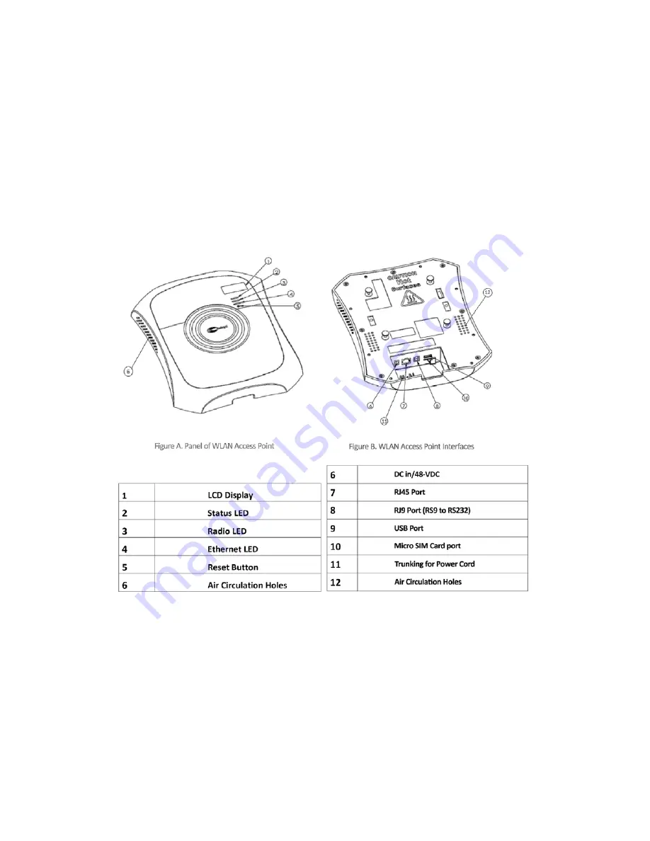
Your Access Point Hardware Features
a.
Power can be supplied either through a 48VDC adaptor, or an IEEE 802.3at PoE+
(PoE plus) Switch port that can supply up to 25W power over Ethernet cable
inserted into the RJ45 port (
B7
). We recommend using the PoE+ for better
management.
b.
If you do not have a PoE+ Switch, you can use the power adaptor that comes with
the AP. The AP’s power cable can be inserted into the DC port (
B6
).
c.
The Ethernet cable is better to use CAT5 or CAT6 class cable, which can be inserted
into the RJ45 port (
B7
).
d.
The Relay2 AP also features a serial port (
B8
), a USB port (
B9
), and an optional SIM
card port (
B10
).
e.
Once the AP is receiving power, it will initiate an LCD/LED startup sequence.
f.
In the LED startup sequence, all three LED lights—Status (
A2
), Radio (
A3
), and
Ethernet (
A4
)—should blink green and then turn solid green.
g.
The AP’s power and Ethernet cables can be trunked into the grooves beneath their
respective ports, as shown below:


