REKOSER RTI Series User Manual Download Page 22

User Manual for RTI series

Quality Warranty Card

In order to ensure high quality, the sine wave REKOSER RTI series inverter must be strictly inspected

before delivery. REKOSER assures the good machine performance and the parts integrity listed in the

warranty card to the users. The free warranty service is available for one year, and the warranty

regulations are as follows:
(I) In case the parts are damaged or have fault within the warranty period since the purchasing of the
machine and such damage or fault has been verified by the technical personnel of REKOSER to take place

in normal use, REKOSER will freely repair the machine and replace relevant parts, but the damaged parts

shall belong thereto.
(II) In case of any following condition listed in the warranty card for the machine, the warranty period
shall be automatically expired.
1. Alter company trademark;
2. Damage is caused due to faulty operation, use negligence and negligence factors;
3. Other persons rather than the technical personnel of REKOSER optionally start up the machine for

repair, refit the machine, obliterate or remove machine number or seal strip;
4. The machine is not installed according to the installation instructions of the manufacturer.
(III) Please properly reserve this card and show this card and the purchasing receipt note (invoice) to the

technical personnel for repair.
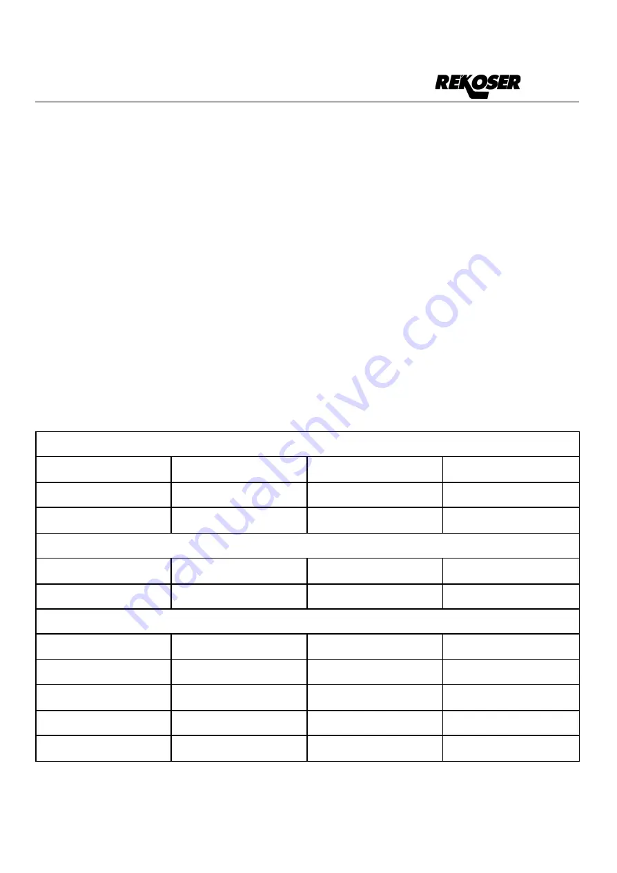
Contact information

Name and surname

Product model

Telephone

Email

Company

Address

Product information

Serial Number

Product model

Purchasing time

Invoice number

Maintenance Record

Date

Description

Performed by

Worker Signature

Note: please make one copy with an o cial seal after the user information is written and send it back to

the Market Department of the Company for archiving.

22

Summary of Contents for RTI Series

Page 1: ...RTI Series Telecom Sine Wave inverter User Manual...

Page 2: ...tery pack installation firmly connect the battery pack according to the connection method and sequence specified in the battery installation instruction It is forbidden to connect the positive and neg...

Page 3: ...al index 8 Chapter III Structure and Principle 11 3 1 Hardware structure and working principle 11 3 2 Operation mode 11 3 2 1 AC power supply mode 11 3 2 2 DC power supply mode 12 3 3 Appearance and i...

Page 4: ...tor light and button definition 18 6 2 Indicator light display list 18 6 3 Specification for LCD display menu 19 Chapter VII Alarm and Monitoring 20 7 1 Remote control and alarm 20 7 1 1 Interface def...

Page 5: ...ries inverter in a small and narrow unventilated space or else the power supply will be overheated 2 In order to avoid fire and electric shock please be sure that all cables have good electrical chara...

Page 6: ...intelligent microcomputer CPU control technology and advanced control theory as well as mature and stable high frequency inversion mode in order to rapidly respond to the external environment change...

Page 7: ...is under inverter output mode during normal operation and automatically switches to mains by pass output during the occurrence of DC input fault This product also has the function of LED LCD status di...

Page 8: ...VAR 220 230 5KVAR 6000VA Not available 48 230 6KVAR 110 230 6KVAR 220 230 6KVAR 8000VA Not available 48 230 8KVAR 110 230 8KVAR 220 230 8KVAR 10000VA Not available 48 230 10KVAR 110 230 10KVAR 220 230...

Page 9: ...ynamic response time 5 load 0 100 Power factor PF 0 8 Overload capacity 100 120 60s 121 150 10s Inversion efficiency 80 resistive load 85 By pass conversion time ms 6ms Workin g enviro nment Dielectri...

Page 10: ...off voltage 40V 60V Cutoff voltage 90V 135V Cutoff voltage 180V 275V Startup voltage 22V 28V Startup voltage 45 5V 57V Startup voltage 104V 131V Startup voltage 208V 260V Rated input current A 1KVA 42...

Page 11: ...and takes CPU as the master control chip thus realizing the perfect combination of the advanced intelligent control and the mature and stable inverter mode Functional block diagram 3 2 Operation mode...

Page 12: ...DC dominated inverter working mode under normal condition DC dominated inverter is under inverter output status all the time in case of DC fault it switches to mains by pass 3 3 Appearance and indicat...

Page 13: ...ting requirement of GB3859 2 93 Verticality no vibration with the vertical gradient not exceeding 5 degrees Class of pollution Class II The system shall be installed in the cool and dust free operatin...

Page 14: ...d shall preferably not exceed 3 months During equipment installation it is necessary to deliver the equipment to the installation site and then remove the external package At this moment it is necessa...

Page 15: ...e positive and negative electrodes Hot line operation shall be forbidden in order to avoid such accidents as short circuit and striking which may endanger personal safety and equipment safety 2 AC inp...

Page 16: ...y to the load 5 1 2 Daily operation Only the startup shutdown switch on the machine is operated for daily startup For shutdown it is necessary to first turn off the load and then turn off the inverter...

Page 17: ...which can be set through the LCD namely selecting Turn Off turn off is permanent and there will be no audible alarm for any new fault in the sound control option Operators can directly press the ENT t...

Page 18: ...green Quick flashing red Slow flashing red Normally red Buzzer No One sound every 3s One sound every 3s One sound every 3s Battery light Green Red Status Normal DC voltage High DC voltage Low DC volta...

Page 19: ...User Manual for RTI series 6 3 Specification for LCD display menu 19...

Page 20: ...User Manual for RTI series Chapter VII Alarm and Monitoring 7 1 Remote control and alarm 7 1 1 Interface definition The contact capacity of each group of the dry contacts shall not exceed 60 V 0 5A 20...

Page 21: ...d whether the voltage of each point is normal etc Consult with the technical personnel of the manufacturer Mains switchin g fault Unable to switch Too high or too low utility supply voltage Use a univ...

Page 22: ...for the machine the warranty period shall be automatically expired 1 Alter company trademark 2 Damage is caused due to faulty operation use negligence and negligence factors 3 Other persons rather tha...

Page 23: ......

Page 24: ...REKOSER C Cedro s n nave 6 Pol Ind La Ermita 18230 Atarfe Granada Spain 34 958042973 info rekoser com www rekoser com...

Reviews: