background image

50

Regency GF900L-1 Gas Fireplace

PARTS LIST

parts list

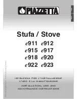
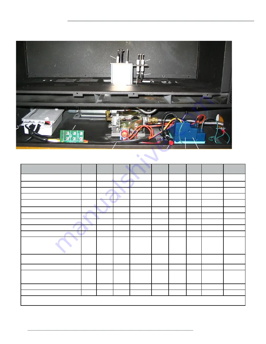
ELECTRONIC COMPONENTS PARTS LIST

Note:

 Depending on the model, the diagram below may not be exactly as shown - for reference purposes only.

910-936

910-082

910-088

910-089

910-084

910-101

910-526

910-080

910-521, 910-522, 910-523

910-912

910-083

911-121

910-514

FG38

FG39

PG33

PG36 / 

PG36D

PG121/

PG131

GFI300L

 IG34

GF900L/C

GF1500L

910-909  

Fan Resistor

910-936 

 Intermittent Pilot

N/A

N/A

N/A

911-146 

 Intermittent Pilot

N/A

N/A

N/A

N/A

N/A

N/A

N/A

910-082 

 Direct Spark Ignitor

N/A

N/A

N/A

N/A

N/A

N/A

N/A

N/A

910-089  

Flame Cable

N/A

N/A

N/A

N/A

N/A

N/A

N/A

N/A

910-088  

Spark Cable

N/A

N/A

N/A

N/A

N/A

N/A

N/A

N/A

910-084 

 Control Box

N/A

N/A

N/A

911-101 

 Control Box

N/A

N/A

N/A

N/A

N/A

N/A

910-527  

Manual Control Switch

N/A

N/A

N/A

N/A

N/A

N/A

910-080  

Valve

910-521  

Control Box Cable 

 (1)

910-522  

Control Box Cable  

(2)

910-523  

Control Box Cable  

(3)

910-525  

Control Box Cable  

(4)

*N/A

(2)

(1)

(1)

(3)

N/A

(2)

N/A

N/A

910-912 

  Ignition Module to Valve 

Cable

N/A

N/A

911-183

 Reset Switch

N/A

910-083  

Ignition Module  

(1)

911-121 

 Ignition Module 

 (2)

(1)
(2)

(2)

(2)

(2)

(2)

(2)

(2)

(2)

(2)

910-514  

Jumper Wire

N/A

910-935 

  Manual Control Switch

N/A

N/A

N/A

N/A

N/A

**Note:

 The Control Box Cable wires for the FG38 come separately: 910-502, 910-505, 910-506, 910-507, 910-509


911-183

Summary of Contents for GF900L-NG1

Page 1: ...p these instructions for future reference MODELS GF900L NG1 GF900L LP1 GF900L ULPG1 LISTINGS AND CODE APPROVALS These gas appliances have been tested in accordance with AS4553 NZS5262 NZS5266 and have been certified by the AustralianGas Associationforinstallationand operation as described in these Installation and Operating Instructions Must be installed as per AS NZS5601 2013 Your unit should be ...

Page 2: ...des helps to differentiate one Remote Control Handset from another so that only the control box with a matching ID code will respond to the appropriate Remote Control Handset To match the control box the following steps are to be followed 1 Ensure the Remote is switched OFF 2 Remove main power to the control box 3 Reconnect main power to the control box 4 Press and hold the PROG and FAN buttons si...

Page 3: ...instructions GF900 25 Unit Installation with Horizontal Termination 26 102mm x 175mm Flueing 26 Unit Installation with Horizontal Termination 27 Unit installation with Vertical Termination 28 102mm x 175mm Flueing 28 High Elevation 29 Gas Line Installation 29 Pilot Adjustment 29 Gas Pipe Pressure Testing 29 Wiring Diagram 30 Conversion from NG to LP ULPG 31 845 S I T Valve Description 33 Aeration ...

Page 4: ...NCE DO NOT 908 602a Rev C Part 919 117 Colour Black on Grey Size 100 7 W x 2 7 H Mar 22 12 draft for approval May 30 12 Made changes as per test report June 25 12 Added AGA Approval Dec 23 13 Updated E Aus address Sept 23 15 Changed to MJ hr added NZ address Feb 16 16 Rev C added a 1 Serial Number Regency Gas Fireplace 405 Electrical 240V 50 Hz 919 117c Gas Type NG LP ULPG Model GF900L NG1 GF900L ...

Page 5: ...L 1 Gas Fireplace 5 1192mm 641mm 989mm 438mm Verona Surround Faceplate Dimensions DIMENSIONS dimensions UNIT DIMENSIONS 259mm 76mm 500mm 1091mm 995mm 889mm 332mm 536mm 113mm 14mm 560mm 522mm 160mm 1082mm 795mm 725mm ...

Page 6: ...e 10 Be aware of electrical wiring locations in walls and ceilings when cutting holes for termination THIS UNIT MUST ALWAYS TERMINATE FLUE DIRECTLY TO THE OUTDOORS IMPORTANT MESSAGE SAVE THESE INSTRUCTIONS The GF900L Direct Vent Fireplace must be installed in accordance with these instructions Carefully read all theinstructionsinthismanualfirst Consultthe authority having jurisdiction to determine...

Page 7: ...ard and optional features Refer to the following sections a Log Install b Faceplate Door Frame Overlay c Remote Control 9 Final check Before leaving this unit with the customer the installer must ensure that the appliance is firing correctly and operation fully explained to customer INSTALLATION CHECKLIST 1 Locate appliance a Room location Refer to Locating Your Gas fireplace section b Clearances ...

Page 8: ...f Fireplace Opening B Sidewall on one side 146mm Side of Fireplace Opening C Ceiling room and or alcove 1003mm Top of Fireplace Opening D Mantel Depth max 305mm 667mm Above Fireplace Opening E Alcove Width 1480mm Sidewall to Sidewall Minimum F Alcove Depth 787mm Front to Back Wall Maximum G From Floor 610mm Top of Fireplace Opening Note 0 No hearth required Installed close to ceiling Flue Clearanc...

Page 9: ...e mantel and the facing is high quality or the paint may discolour MANTEL LEG CLEARANCES Combustible mantel leg clearances as per diagram Combustible Material 152mm 305mm 0 Non combustible Facing To Unit Base 667mm 610mm 254mm 660mm Top of Fireplace Opening 508mm 305mm 606mm 438mm Combustible Stud On Edge 25mm 502mm Nailing Flange Allowable mantel leg projection 181mm 254mm 330mm 38mm MANTEL LEG 8...

Page 10: ...iling strips set as far forward on the firebox as possible The nailing strips can be adjusted back up to 38mm to allow for varying thicknesses in non combustible material wall finishes INSTALLATION ACCESS PANEL The unit is equipped with a removable access panel for pre finish installation of optional components this panel is located on the lower front face 1 Remove 6 screws to remove access panel ...

Page 11: ... L Gas Connection Opening Width 89mm Framing depth measurement is noted with the nailing strips set as far forward on the firebox as possible The nailing strips can be adjusted back up to 38mm to allow for varying thicknesses in non combustible material wall finishes NOTE A minimum thickness of 12mm non combustible facing board compliant with AS1530 1 and AS1530 3 is required A B C D G H Non Combu...

Page 12: ... 2 screws on each nailing strip adjust and retighten screws 4 Attach both vertical studs 466 126 to the vertical timber studs and secure using 6 screws 2 at bottom 2 at top and 2 on sides as shown NOTE Ensure the flat side of the steel stud is facing the timber framing 466 126 Flat side out 5 Secure horizontal steel header stud 466 128 with 2 screws per side as per diagram 6 Slide the unit into po...

Page 13: ...ed with non combustible required materials to specific dimensions above and aroundtheunits Thisisduetotheseareasreachinghighertemperature levels than required acceptable for a combustible material To obtain the best most durable finish around your fireplace this calls for a high level of care and attention to the preparation and finish around this appliance using only the highest quality materials...

Page 14: ...materials See Clearances section Combustible materials can be laid against the side and back standoffs and the stove base 4 Non combustible material ie tile slate etc may be brought up to and overlap the unit top and bottom ensuring that the maximum thickness does not go beyond the 38mm as shown in the diagram below The faceplate will not be able to be mounted if finished material is beyond 38mm 1...

Page 15: ... appliance must be installed on a flat solid continuous surface For example a wood metal or concrete floor or in a raised on the wall application The appli ance must be installed on a metal or wood base extending the full width and depth of the appliance NOTE Ifraisingtheunit thentheminimum height measurement A on page 11 of the framing dimensions must be adhered to For example Unit raised 300mm t...

Page 16: ...Regency GF900L 1 Gas Fireplace installation EXTERIOR FLUE TERMINATION LOCATIONS FIGURE 6 2 in part LOCATION OF FLUE TERMINALS OF BALANCED FLUE AS NZ 5601 2013 ROOM SEALED FAN ASSISTED OR OUTDOOR APPLIANCE ...

Page 17: ...liances over 250MJ h input 1500 1500 All fan assisted flue appliances in the direction of discharge 1500 k From a mechanical air inlet including a spa blower 1500 1000 n Vertically below an openable window non mechanical air inlet or any other opening into a building iwth the exception of sub floor ventilation Space heaters up to 50MJ h input 150 150 Other appliances up to 50 MJ h input 500 500 Ap...

Page 18: ...iagrams refer to the following instructions 1 Remove the glass door and inner panels see instructions in this manual 2 Remove6screws 3front 3back toremoveheatbaffletoaccessrestrictor plate 3 Remove the screws that hold the flue restrictor in place FLUE RESTRICTOR POSITION Heat Baffle 4 Adjust the flue restrictor plate to the required flue restrictor position as per the diagrams shown below 5 Once ...

Page 19: ...GEMENT FOR HORIZONTAL TERMINATIONS The diagram shows all allowable combinations of vertical runs with horizontal terminations using one 90o two 45o elbows equal one 90o elbow Note Must use optional rigid pipe adapter Part 510 994 when using Simpson Dura Vent Only Maintain clearances to combustibles as listed in Clearances section Horizontal flue must be supported every 0 9m A flue guard should be ...

Page 20: ...flexible outer liner Kit length 2 102mm flexible inner liner Kit length 3 spring spacers 4 thimble 5 AstroCap termination cap 6 screws 7 tube of Mill Pac 8 plated screws 9 S S screws 8 x 1 1 2 drill point 946 516 3 m FLUEING ARRANGEMENTS HORIZONTAL TERMINATION FLEX Regency Direct Vent System These flueing systems in combination with GF900L have been tested and listed as a Direct Vent system by AGA...

Page 21: ...1mm When using Rigid Flue other than Simpson Dura Vent 3 screws must be used to secure rigid pipe to adaptor WARNING Do not combine flueing components from different flueing systems However use of the the AstroCapTM and FPI Riser is acceptable with all systems This product has been evaluated by Intertek for using a Rigid Pipe Adaptor in conjunction with Duravent Direct Vent The FPI AstroCapTM and ...

Page 22: ... or two 45o elbows is permitted 2 Minimum distance between elbows is 305mm Maintain clearances to combustibles as listed in the Clearances section Horizontal vent must be supported every 0 9m Must use optional rigid pipe adaptor Part 510 994 when using Duravent systems A vent guard should be used whenever the termination is lower than the specified minimum or as per local codes Flex system can onl...

Page 23: ...r installations using FPI flueing systems as well as Simpson Dura Vent Direct Vent is a proprietary trademark of FPI Fireplace Products International Ltd Dura Vent and Direct Vent are registered and or proprietary trademarks of Simpson Dura Vent Co Inc Galvanized pipe is desirable above the roofline due to its higher corrosion resistance Continue to add pipe sections through the flashing until the...

Page 24: ...mbustibles as listed in the Clearances section in the manual Horizontal flue must be supported every 1M Refer to the Flue Restrictor Position section for details on how to change the flue restrictor from the factory setting of Set 0 or Set 3 if required Note For ULPG Flue Restrictor Set to 0 75mm open FLUEING ARRANGEMENT FOR VERTICAL TERMINATIONS Vertical Venting with One 1 90o Elbows 1 90o 2 45o ...

Page 25: ...ace using non combustible brac ing to stop movement On penetration of roof fit an appropriate flashing or weather seal to suit the roofing material ensure all joints outside are sealed with appropriate sealer 6 Fit gas cowl 46DVA VCH 9 or flomet cap 946 651 ensuring inner and outer flue pipes are sealed 7 Start heater and run for at least 15 minutes to check flue seal If operational issues are not...

Page 26: ...ing inner and outer flue collar Fasten to the outer collar only with the 3 supplied screws drilling pilot holes will make this easier 4 Level the fireplace and fasten it to the framing using nails or screws through the top and side nailing strips Note For best results and optimum performance with each approved venting system it is highly recommended to apply Mill Pac sealant to every inner pipe co...

Page 27: ...he cap indicating which way is up This will position the termination cap with proper down slope for draining water Fasten the cap to the outer wall with the 4 supplied screws 6 Pull the centre inner and outer flex liner out enough to slip over the flue collars of the fireplace You may wish to cut the liner shorter to make it more workable Do not bend liner more than 90o The liners must slip over t...

Page 28: ...he elbows and possible separation Metal Wall straps can be used Do not combineflueingcomponentsfromother manufacturers Galvanizedpipeisdesirableabovetheroofspace due to its higher corrosion resistance Continue to add pipe sections through the flashing until the height of the flue cap meets the minimum height requirements specified in Dia 4 or local codes Note that for steep roof pitches the vertic...

Page 29: ...r local authorities When using copper or flex connectors use only approved fittings Always provide a union so that gas lines can be easily disconnected for servicing Flare nuts for copper lines and flex connectors are usually considered to meet this requirement NOTE A shutoff valve should be supplied in or near the unit or as per local codes for ease of servicing this appliance GF900L NG SYSTEM DA...

Page 30: ...E SIGMA 845 EARTH EARTH JUMPER 2 12 1 10 11 9 RED BLUE GREEN BROWN 4 5 3 2 1 YELLOW 3 YELLOW BLUE EARTH BROWN LOW SPEED WHITE RED BLACK FAN 5 3 4 BROWN VIOLET BLUE RED 1 3 2 4 WHITE YELLOW VIOLET BLACK 5 6 1 2 BROWN BLUE VIOLET RED BLACK WHITE YELLOW VIOLET ORANGE ORANGE MODULATING 7 8 6 5 4 3 VALVE RESET SWITCH NC BLACK BLACK 2 1 COIL MODULE SPARK MODULE EARTH MODULE FLAME ORANGE ORANGE 5 4 ORANG...

Page 31: ...RSION KIT 466 967 FROM NG TO ULPG FOR GF900 USING SIT 845 NOVA GAS VALVE THIS CONVERSION MUST BE DONE BY A QUALIFIED GAS FITTER IF IN DOUBT DO NOT DO THIS CONVERSION 5 Remove rear log tray by removing 3 screws as shown in Diagram 3 below FOLLOWING STEPS FOR GF900C 6 Remove glass crystals and stones if installed 7 Remove 3 screws in locations shown below to remove burner tray Each Kit contains one ...

Page 32: ...by undoing the 3 screws Manoeuvre through antenna 18 Reverse steps 15 14 for both units 19 Adjust the air shutter opening See page 33 for Aeration Adjust ment For GF900C reverse steps 8 6 and 1 For GF900L reverser steps 5 1 20 Turn on gas supply and plug in power cord Control Box Cover Antenna Jumper Location 17 Remove the jumper using pliers Jumper Diagram 4 Remove Pilot Cap Pilot Cap Pilot Orifi...

Page 33: ...ating Screw in the nut B to increase the outlet pressure and screw it out to decrease it Use a 10 mm wrench NOTE The outlet pressure must be set to maximum 2 49 kPa Minimum pressure Remove one of the cables connected to the electric modulator While holding the nut B with a wrench screw in the screw C to increase the pressure and screw it out to de NOTE The outlet pressure must be set to minimum 1 ...

Page 34: ...ire hazard 6 Plan the location of the fireplace and the warm air duct runs see diagram 1 as a guide for possible duct runs and locations Diagram 1 Guide for possible air duct runs and locations Keep duct length and number of bends to a miniumum Maximum duct length is 9 0m The Extension Kit contains a maximum of up to 4 5m Please purchase the Fan Duct Extension Kit to increase the 9 0m MINIMUM FRAM...

Page 35: ...egister to the Fan Housing See diagram 4 8 Remove the knock out on the top of the unit Remove the second knock out that is below top knockout 9 On the top of the unit bend the 3 tabs up Insert the Duct collar Secure the collar to the 3 tabs with screws 10 You are now ready to attach fan duct to the unit Slide the ducting over the collar and secure with screws 11 Final step is to double check the f...

Page 36: ...AM Caution Ensure that the wires do not touch any hot surfaces and are away from sharp edges AlternateSwitches Mayusethefollowing Checkwithlocalauthoritiesandelectrician CLIPSAL 203 2E45 OUD Dimmer CLIPSAL 2031 VF3CSF 3 Speed CAUTION Labelallwirespriortodis connection when servicing controls Wiringerrorscancauseimproperand dangerous operation Wire Nut Wire Nut Wire Nut Rheostat Wire Nuts Wire Wire...

Page 37: ...nder warranty Log kit 466 930 contains the following pieces 1 Line up locators on Log 1 with corresponding locators on Log Tray as shown in Diagram 2 2 Line up locators on Log 2 with corresponding locators on Ceramic Log Burner as shown in Diagram 3 3 Line up locator on Log 3 with corresponding locator on Ceramic Log Burner as shown in Diagrams 4 and 5 Diagram 2 Diagram 3 Diagram 4 Diagram 5 3 4 5...

Page 38: ...d Log 3 as shown in Diagram 9 8 Line up locator on bottom of Log 7 with locator on Ceramic Log Burner as shown in Diagram 10 6 Log 5 final position shown in Diagram 8 6 Log 8 in final position shown in Diagram 11 Place supplied embers over burner screw holes in locations shown below Diagram 7 Diagram 8 Diagram 9 Diagram 10 Diagram 11 Log 8 and ember locations Diagram 6 3 6 1 3 8 7 4 4 1 1 2 2 2 4 ...

Page 39: ...low to remove front trim piece 3 Reverse steps to reinstall 1 Remove front trim piece see instructions above 2 Remove two 2 screws in locations shown below to release panel clips 3 Remove panels by sliding out 4 Reverse steps to reinstall Front Trim Piece Panel Clip Screw Locations Panel Clip Diagram 1 Front Trim Screw Locations INNER PANEL REMOVAL INSTALLATION FRONT TRIM REMOVAL INSTALLATION ...

Page 40: ...e the first mounting slot the one clos est to the door frame overlay out of the 3 so that the faceplate and door frame overlay are flush with one another See diagram 2 1 Install the fascia to the unit by hooking the left and right side mounting brackets into the mounting slots at the side ofthe firebox as shown below Diagram 3 Diagram 4 Deflector Installed NOTE When installing the stainless steel ...

Page 41: ...een Mesh over Inner Door Frame as shown in Diagram 1 3 Install Screen and Inner Door Frame to unit over glass door frame as shown in Diagram 3 Lower gently once in position over glass door frame 2 Bend Tab on Screen Mesh to 90º as shown in Diagram 2 Secure to Inner Door Frame with one 1 screw as shown in Diagram 2a Diagram 1 Diagram 3 Diagram 2 Diagram 2a ...

Page 42: ...any finishing that protrudes slightly beyond the faceplate Warning Turn off the unit by way of the wall switch or remote Allow unit to cool at least 10 min prior to removing the faceplate Diagram 1 Glass Surround Install Diagram 3 Final Install Diagram 2 adjustments 1 4 6mm 1 2 13mm Use first notch in bracket for standard installation 919 615 11 05 15 1 OPTIONAL FINISHING TRIM INSTALLATION tooltip...

Page 43: ...is lit it may cause condensation and fog the glass This condensation is normal and will disappear in a few minutes as the glass heats up DO NOT ATTEMPT TO CLEAN THE GLASS WHILE IT IS STILL HOT DO NOT BURN THE APPLIANCE WITH OUT THE GLASS FRONT IN PLACE FAN OPERATION Set the fan speed on the control panel at the top rear of the unit to adjust to the desired speed Pressing and releasing the plus FAN...

Page 44: ...rating a live fuel effect designed to oper ate with blue flames with slight yellow tips may exhibit slight carbon deposition FOR YOUR SAFETY READ BEFORE LIGHTING A BEFORE LIGHTING smell all around the appliance areaforgas Besuretosmellnexttothefloorbecause some gas is heavier than air and will settle on the floor WHAT TO DO IF YOU SMELL GAS Do not try to light any appliance Do not touch any electr...

Page 45: ...wn in Diagram 1 4 Remove burner by removing 2 screws in locations shown below 7 Loosen three 3 screws to remove heat deflector shown in Diagram 5 8 Remove two 2 screws to remove fan shown in Diagram 6 9 Reverse steps to reinstall fan 6 Remove access panel by removing eight 8 screws in locations shown in Diagram 4 Diagram 3 Log Tray screws Diagram 5 Heat Deflector Screws Diagram 6 Fan Screws Diagra...

Page 46: ...inspection of the venting system semi annually Recommended areas to inspect as follows 1 Check the Flueing System for corrosion in areas that are exposed to the elements These will appear as rust spots or streaks and in extreme cases holes These components should be replaced immediately 2 Remove the termination cap and shine a flashlight down the Flue Remove any bird nests or other foreign materia...

Page 47: ...n after approx 1 minute Then turn on again NOTE On initial light up this may occur a number of times until any residual air is purged from the gas line through the burner system It is essential the required waiting time as stated in the manual is observed prior to attempting re ignition After rese翿 ng ignition module unit still not Turn burner switch to ON fans will operate within 5 secs listen fo...

Page 48: ...e other lower door latch 6 Pull the bottom of the door towards you until the door is angled away from the firebox by about 30 Lift the door up and over the upper door hooks 7 To install the glass door reverse steps 1 Insert the door tool into the lower door latch WARNING Do not operate the appliance with the glass panels removed cracked or broken Replacement of the glass panels should be done by a...

Page 49: ...e tray and reverse steps Diagram 4 Valve Tray Screw Locations Diagram 5 Valve Tray Removal 1 Remove faceplate inner frame glass door front trim piece and inner panels see instructions in this manual 2 Remove logs 3 Remove burner side panels by lifting out as shown in Diagram 1 4 Remove burner by removing 2 screws in locations shown below Diagram 3 Log Tray screws Diagram 1 Burner Side Panels Diagr...

Page 50: ...A N A N A N A N A N A 910 089 Flame Cable N A N A N A N A N A N A N A N A 910 088 Spark Cable N A N A N A N A N A N A N A N A 910 084 Control Box N A N A N A 911 101 Control Box N A N A N A N A N A N A 910 527 Manual Control Switch N A N A N A N A N A N A 910 080 Valve 910 521 Control Box Cable 1 910 522 Control Box Cable 2 910 523 Control Box Cable 3 910 525 Control Box Cable 4 N A 2 1 1 3 N A 2 ...

Page 51: ...anel Bracket 15 466 034 Right Panel Bracket 16 396 038 Bottom Door Latch Retainer Part Description 17 396 037 Bottom Door Latch 18 466 576 P GF 900 Valve Assy LP 466 574 P GF 900 Valve Assy NG 21 466 044 Front deflector 23 466 060 Left Panel 24 466 061 Right Panel 25 466 071 Left ceramic filler 26 466 072 Right ceramic filler 30 476 062 Panel Clip 31 Rear Panel 466 967 Conversion Kit LPG ULPG 911 ...

Page 52: ...52 Regency GF900L 1 Gas Fireplace PARTS LIST parts list 23 30 17 21 13 18 14 12 15 24 9 5 5 1 2 3 MAIN ASSEMBLY ...

Page 53: ...Part Description 32 467 922 Inner door frame Black w Screen 467 932 Inner door frame Stainless w Screen 33 467 544 Door Frame Overlay Black 34 467 938 Fascia and Door Frame Black w Screen 467 936 Fascia and Door Frame Stainless Steel w Screen 467 951 Fascia Black Glass not shown ...

Page 54: ...components Ignition Control Boards Wiring Switches Fans Fan Control Module Battery Pack Remote Control Systems 1 Enamel Panels 1 Venting Venting Components 1 All Stainless steel surrounds 1 All Firebox Media Crystals Fire beads Volcanic Ceramic Spa Stones 1 All hardware 1 Mesh Glass Safety Barriers 1 Accent Light Bulbs 1 Glass Crazing 1 After the original warranty coverage for any of the parts abo...

Page 55: ...general practice of FPI to charge for larger higher priced replacement parts and issue credit once the replaced component has been returned to FPI and evaluated for manufacturer defect If a consumer has a unit installed outside an accredited distributor dealer or pre approved service agent s service area or the closest approved service agent is situated more than thirty 30 kilometres from the inst...

Page 56: ...r movement expansion and contraction of the steel is normal and is not covered under the terms of this warranty Freight damages for products or parts are not covered under the terms of the warranty Porcelain Enamel Absolute perfection is neither guaranteed nor commercially possible Any chips must be reported and inspected by the authorised selling dealer within three 3 days of installation Any dam...

Page 57: ...to at the option of the supplier one or more of the following i replacement of the goods or the supply of equivalent goods ii the repair of the goods iii the payment of the cost of replacing the goods or of acquiring equivalent goods or iv equivalent goods or v the payment of the cost of having the goods repaired b To the extent that services supplied by the supplier are services other than servic...

Page 58: ...ervices Fireplace Products Australia Pty Ltd 1 3 Conquest Way Hallam VIC Australia 3803 Phone 61 3 9799 7277 Fax 61 3 9799 7822 To obtain warranty service in Western Australia and or New Zealand please contact one of our authorised distributors in those areas Western Australia Air Group Australia 28 30 Division St Welshpool WA Australia 6106 Phone 08 9350 2200 Fax 08 9353 4225 New Zealand Aber Hol...

Page 59: ...k to us and we will register the warranty for you It is important you provide us with all the information below in order for us to serve you better Warranty Registration Form or Register online immediately at the above Web Site Warranty Details Serial Number required Purchase Date required mm dd yyyy Product Details Product Model required Dealer Details Dealer Name required Dealer Address Dealer P...

Page 60: ...60 Regency GF900L 1 Gas Fireplace ...

Page 61: ...Regency GF900L 1 Gas Fireplace 61 NOTES notes ...

Page 62: ...62 Regency GF900L 1 Gas Fireplace NOTES notes ...

Page 63: ...Regency GF900L 1 Gas Fireplace 63 ...

Page 64: ...formation Dealer Name Address _______________________________________________ ___________________________________________________________________ Installer ____________________________________________________________ Phone ____________________________________________________________ Date Installed _______________________________________________________ Serial No ___________________________________...

Reviews: