A Regal Brand
V-Green Automation Adapter Kit
Installation Manual and User’s Guide
For use with Century® V-Green Variable Speed Motors
Page 1: ...A Regal Brand V Green Automation Adapter Kit Installation Manual and User s Guide For use with Century V Green Variable Speed Motors...
Page 2: ...emarks and registered trademarks are the property of their respective companies The information in this document incorporates proprietary rights and is not to be duplicated wholly or in part without t...
Page 3: ...utomation system output connectors 14 Using automation system relays 15 Connecting to Input side of Relays 15 Connecting to Output side of Relays 16 Output Signal Powered by Automation Adapter 16 Outp...
Page 4: ...er property DANGER DANGER indicates a hazardous situation which if not avoided will result in death or serious injury WARNING WARNING indicates a hazardous situation which if not avoided could result...
Page 5: ...1 Digital Input Cable 2517463 001 4 Lead Cable 2517465 001 25 FT RS 485 Connecor 2511130 001 1 Conduit Fitting 2017587 002 1 Terminal Box Cover Assembly 1 Plug 2514059 001 4 Screw Driver 2517831 001...
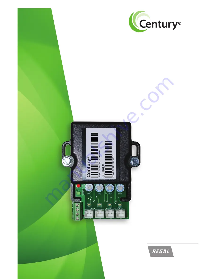
Page 6: ...r to control and experience the full variable speed capability of a V Green product through an existing automation system OVERVIEW System Adapter Control Board Figure 2 Figure 1 4 Access to the connec...
Page 7: ...er RS 485 Input CON1 Digital Inputs IN1 IN2 IN3 IN4 9 30 VAC VDC 2mA Typical 22mA MAX Connect to relay coil or valve control of automation system PWM IN1 ONLY 70 125Hz 5 97 Duty Cycle Figure 4 Figure...
Page 8: ...duct Failure to comply with this may result in death serious personal injury or property damage NOTE Refer to manufacturer s instructions for wiring on all other products other than the automation ada...
Page 9: ...move the plastic wiring cover inside the terminal box one screw Figure 7 Internal Plastic Cover Removed 7 3 Remove the 3 8 conduit hole plug with a 5 16 Allen wrench Figure 6 3 8 Conduit Hole Plug Rem...
Page 10: ...nterface from the controller 4 screws Figure 9 User Interface and Rubber Gasket Removed 8 5 Disconnect the 4 pin communication connector J103 by pulling up on the connector Figure 8 Communication Conn...
Page 11: ...N 2511130 001 on the cable See the wiring diagram Tighten the seal nut on the conduit fitting until snug Figure 11 Communication Connection Wiring Figure 12 Cable Installed 9 7 Install the Conduit Fit...
Page 12: ...adapter to function REFER TO THE V GREEN MOTOR USER MANUAL FOR DIP SWITCH POSITIONING 9 Replace the plastic cover inside the terminal box one screw 10 Attach New Gaskets to new terminal box cover Figu...
Page 13: ...Assemble the new metal terminal box cover 2 screws Plug the four User Interface mounting holes with the plastic clips PN 2514059 001 Figure 15 Terminal Box Cover and Clips Installed 11 Mounting Holes...
Page 14: ...on the back of the adapter Place unit so that the orientation of the input connectors are downward NOTE Automation adapter wiring is all low voltage choose a mounting location away from all high volta...
Page 15: ...source If you choose not to power the automation adapter from the V Green motor J103 low voltage power supply the automation adapter can be powered from any 10 14 VDC alternate power supply Figure 17...
Page 16: ...ions which carry line voltage capable of causing personal injury or damaging the equipment if contact is made Power should be turned off when accessing these areas Failure to connect the automation ad...
Page 17: ...e side of Relays Connect IN1 to Relay 1 or any relay from the Automation System Repeat this for IN2 IN3 and IN4 using different automation system relays for each input Figure 20 Automation adapter con...
Page 18: ...automation adapter board CON1 run a wire to the input on desired relays Run the output of the relay to the right pin of an input on the automation board IN1 IN4 Connect IN1 IN4 left pin with COM on C...
Page 19: ...ide of the power source DC to the input on the desired relays Run the output of the relay to the right pin of an input on the automation board IN1 IN4 Connect IN1 IN4 left pin with the common DC of th...
Page 20: ...less than 5 the Automation Adapter will not accept this input It will be treated as if there is no input being applied If the duty cycle is greater than 97 the Automation Adapter will accept this inpu...
Page 21: ...ential Solutions Power is applied to the motor but power LED is not illuminated on the automation adapter Power supply cables are loose at the RS 485 connector Power supply cables are loose at CON 1 o...
Page 22: ...10 14 VDC 30mA Typical Aux Inputs IN1 IN4 9 30 VAC VDC 2mA Typical 22mA MAX PWM Input IN1 Only 70 125Hz 5 97 Duty Cycle Ambient Conditions Storage 30 C to 80 C 22 F to 176 F Operating 0 C to 50 C 32 F...
Page 23: ...rmission of Regal Beloit America Inc Copyright 2013 The text and images in this document are not to be modified without express written permission of Regal Beloit Corporation and or Regal Beloit Ameri...
Page 24: ...Regal Beloit America Inc 1325 Heil Quaker Blvd LaVergne TN 37086 Phone 866 887 5216 Fax 800 468 2062 www pool motors com 2013 Regal Beloit Corporation 2730 6 2013 A Regal Brand...