


17
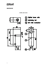
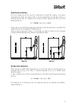
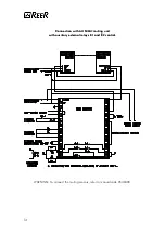
Mechanical installation and optical alignment
The emitter and the receiver must be installed one in front of the other at a distance not to
exceed the effective capacity of the equipment.
A perfect alignment between the emitter and the receiver is essential for the flawless
operation of this device. This operation is facilitated by the presence of a green indicator
LED on the receiver.
CHECKS AND MAINTENANCE.
CHECKS AND MAINTENANCE.
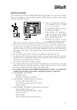
The ULISSE UNC photocell must be used within the working parameters given in the
technical data. At the beginning of each work shift, or at power up, it is necessary to check
the functionality of the photocell through the following procedure: intercept the beam with a
cylinder shaped opaque object with a diameter of 8 mm to be placed at the centre of the
area between the emitter and the receiver, and then in the proximity of both, and make sure
that in each of these cases, the green led “free area light” on the receiver goes off, while at
the same time the control unit output is switched.
The ULISSE UNC photocell has no specific maintenance requirement; at all events, we
recommend cleaning the lenses of the emitter and the receiver at regular intervals, so as to
prevent an excessive quantity of dust from building up and hampering the optical beam
transmission and reception functions, as this may result in the failure of the equipment and
the machine connected to it.
Do not use abrasive or corrosive products, or solvents or alcohol which might damage the
parts to be cleaned.
OPERATING FAULTS.
OPERATING FAULTS.
If any operating faults persist even if the system is turned off and on, check the conditions of
the electrical connections.
Furthermore, make sure that the emitter and the receiver are correctly aligned, and the
lenses are perfectly clean. If these measures are not sufficient to restore correct system
operation, send the equipment to our laboratories, complete with all its parts, specifying
clearly:
•
part number;
•
date of installation;
•
hours of operation;
•
type of installation;
•
fault observed.


