background image

Advanced  Features

16


17

Advanced

Advanced


The  microGain  Matrix  allows  you  to  customize  the  sensitivity  of  your  microRemote  to  better  
accommodate  your  personal  touch.  The  Motor’s  torque  power  is  inversely  related  to  the  smoothness  of  
its  revolutions.  Use  the  UP  and  DOWN  arrows  on  the  Basestation  (page  10)  to  find  a  setting  that  works  
best  for  you.  

Example:  If  you  have  set  the  Basestation  at  a  high  torque  setting,  the  control  knob  will  be  very  sensitive  
and  may  result  in  more  jerky  movement.  Inversely,  if  you  have  the  Basestation  set  very  low  for  
maximum  smoothness,  the  motion  of  the  control  knob  may  not  be  as  responsive  to  subtle  hand  
movements.

microGain  Matrix

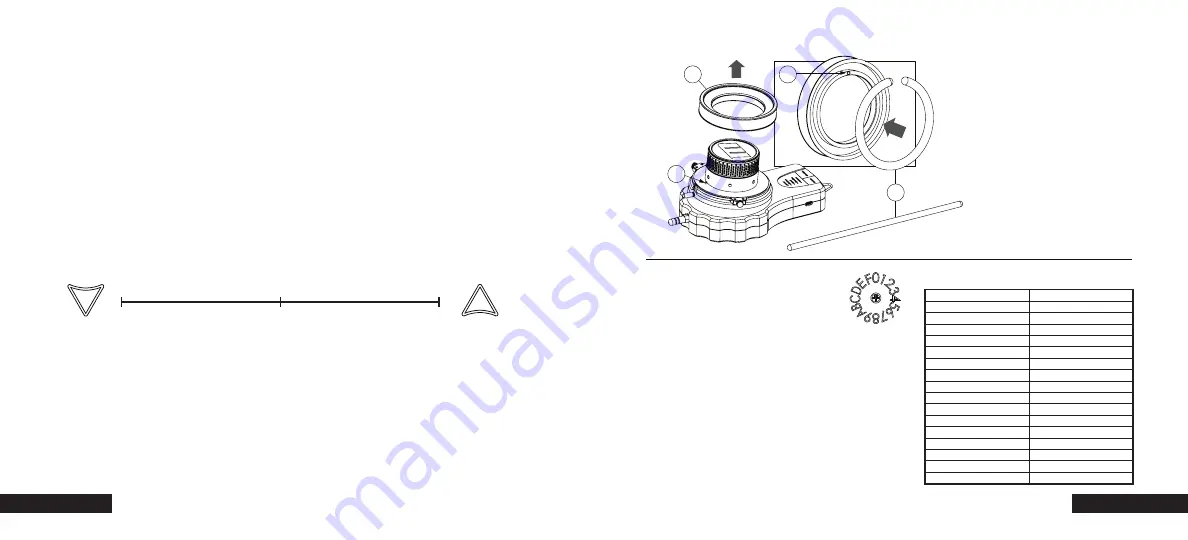
Illuminated  Marking  Disk

Before  adjusting  the  gain,  perform  a  lens  calibration  taking  care  not  to  apply  too  much  pressure  to  the  
lens  gear  from  the  motor.  The  Basestation  comes  set  from  the  factory  at  the  optimized  setting  5.  To  
adjust  the  gain,  tap  either  the  UP  (C)  or  DOWN  (F)  (see  diagram  on  page  10).  After  each  tap  the  red  
LEDs  will  indicate  the  current  setting  by  blinking  in  succession.  Example:  If  you  are  at  setting  3,  the  
LEDs  will  blink  three  times.  Allow  for  the  succession  of  flashes  to  complete  before  tapping  either  up  or  
down  again.  Controller  will  be  unresponsive  during  the  blinks.  

Setting  the  Gain

decreased torque

decreased smoothness

increased smoothness

(Factory Setting)

1

5

10

increased torque

Remove  the  marking  disk  (A)  from  
the  Handheld  by  simply  pulling  it  
straight  off.  Snap  an  illuminating  
flare  (B)  to  initiate  glow,  and  flex  
until  it  glows  evenly  throughout.  
Bend  flare  into  a  circle  and  push  it  
into  place  in  the  inside  ring  of  the  
marking  disk.  When  putting  the  
illuminated  marking  disk  back  into  
place  on  the  Handheld,  

make  

sure  that  the  guide  hole  (C)  
lines  up  with  the  guide  pin  (D).        

D

A

C

B

As  with  any  remote  control  device,  you  may  find  your  
microRemote  picking  up  radio  interference  and  may  
have  to  switch  to  another  channel.  When  changing  the  
radio  channel  selector  dial,  

make  sure  to  set  the  

Basestation  and  Handheld  units  to  the  same  
channel.  

Use  a  flat-­head  screwdriver  to  turn  the  dial  to  

desired  channel.  Cycle  power  (Bastestation  and  
Handheld)  after  channel  change.

If  you  already  know  the  RF  Channel  you  want  to  use,  
consult  the  chart  at  the  right  to  see  how  the  
microRemote  corresponds  with  RF  Channels.

Remote  Channel

RF  Channel

0

11

1

12

2

13

3

14

4

15

5

16

6

17

7

18

8

19

9

20

A

21

B

22

C

23

D

24

E

25

F

26

Radio  Channel  Selector

Summary of Contents for microRemote

Page 1: ...microRemote System User Guide redrockmicro com microremote support redrockmicro com 1 888 214 3903...

Page 2: ...microRemote Technical Specifications 3 Contents The microRemote system complies with Part 15 of the FCC Rules Operation is subject to the following two conditions I this device may not cause harmful...

Page 3: ...or lenses without film pitch gearing Example Installation 5 Quick Start 4 Quick Start Basestation page 10 11 Motor page 12 13 External battery or AC power Power Source Lens Gear Quick Set Up Diagram F...

Page 4: ...flash in sequence and then in unison then settle into their operational mode a Press the CAL button on the Basestation page 10 to enter manual calibration b The CAL indicator LED will blink Press the...

Page 5: ...tion The handheld unit runs on 2 AA batteries included with your purchase Loosen the two screws in the battery compartment cover Remove the cover insert batteries and replace cover To adjust the indic...

Page 6: ...motor cable length limited The Basestation motor controller contains an auto torque feature This feature calculates the ideal amount of torque for optimal performance Please follow these steps EACH TI...

Page 7: ...te almost any lens you shoot with the Torque Motor drive gear is functional on both sides Simply pull the gear out position it on the opposite side line up with peg and push firmly into place Make sur...

Page 8: ...nd slide onto stud as shown Tighten in place Slide blue grip back onto stud and tighten Mounting to a microHandgrip When using the Fingerwheel and reversing motor direction is desired tap the SET butt...

Page 9: ...times Allow for the succession of flashes to complete before tapping either up or down again Controller will be unresponsive during the blinks Setting the Gain decreased torque decreased smoothness in...

Page 10: ...Basestation for tethered control 3 pin 5 pin Fingerwheel Cable Connects Fingerwheel to Basestation Cable Guide We strongly recommend the use of Redrock Micro cables when connecting your remote gear Th...

Page 11: ...nction 1 Motor won t calibrate 2 Motor is loud jittery and or unresponsive a See Motor Communication section above b See page 13 to ensure your motor is properly set up c Adjust microGain until succes...

Page 12: ...BOE CBTFTUBUJPO QBHF t BLF TVSF MFOT HFBS BOE NPUPS HFBST BSF QSPQFSMZ NFTIFE QBHF t BMJCSBUF BGUFS BOZ MFOT DIBOHF PS NPUPS SFQPTJUJPO QBHF t BLF TVSF IBSE TUPQT PO IBOEIFME VOJU BSF OPU TUPQQJOH NP...

Reviews: