POWERSTREAM Ascari -
p. 22 -
1 :
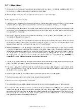
Introduce the blade of the driver into the opening located just
above or bellow the mark.
2 :
Introduce the connector’s terminal inside the cage.
3 :
Remove the screwdriver
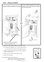
2.14 - Power terminal
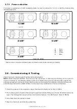
Connections are cage-clamp terminals, to be used as to follow :
- For accessories terminals use a 3
.
5 x 0
.
5mm blade screwdriver
- For power terminal use a
5
.
5 x 0
.
8mm blade screwdriver.
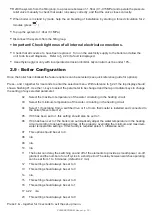
Screw A
5 self-sealing nuts for accessories connections
(Ambience thermostat, outside and/or Domestic Hot
Water sensor and remote cut-out)
Put the self-sealing nut (supplied with the boiler) for
connection to mains from the bottom of the casing.
or
Put the self-sealing nut (supplied with the boiler) for
connection to mains from the top of the casing. In
this case remove the plastic cap and close the hole
below casing using same.
Plastic cap moved from top
to bottom
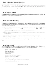
Note : Stripped length of wires must range :
- within 10 and 12 mm for control terminals in 2
.
5
2
- within 17 and 20 mm for main power terminals
.


