Redback 106065 Operation Manual Download Page 1

This safety alert symbol identifies important safety messages in 

this manual. Failure to follow this important safety information may 

result in serious injury or death.

MODEL # 106065 

(106064 Kit)

Operation Manual

!

Part  # 107368 Rev A

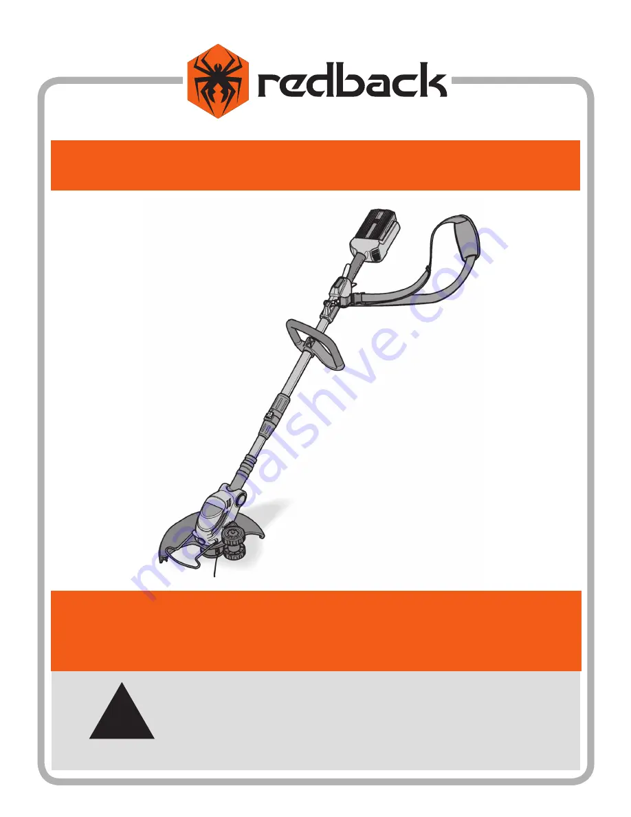
40V Lithium Ion Cordless Line Trimmer

Summary of Contents for 106065

Page 1: ...ies important safety messages in this manual Failure to follow this important safety information may result in serious injury or death MODEL 106065 106064 Kit Operation Manual Part 107368 Rev A 40V Li...

Page 2: ...1100 W 120th Ave Suite 600 Westminster CO 80234 720 287 5182 For Service or Questions Call 1 877 487 8275 720 287 5182 www redbackpowerusa com Redback products are distributed by...

Page 3: ...ssembling and adjusting the shoulder strap 7 Set the shaft length 8 Set the handlebar 8 Set the operating angle 8 Inserting and Replacing the Battery 8 Overview of Components 9 Operation 10 Changing t...

Page 4: ...f you have any questions or concerns about the safe operation of this equipment Intended Use Do not use the line trimmer for any purpose other than for which it was designed Any other use is unauthori...

Page 5: ...rain Always keep hands feet hair and loose clothing away from the line trimmer The battery should be removed before any repairs are attempted Battery tool use and care Recharge only with the charger...

Page 6: ...trimmer are to remind you of important information while you are operating the unit Make sure all safety warning decals are attached and in readable condition Replace missing or defaced decals Contac...

Page 7: ...aching the Running Wheel Insert the running wheel into the holder on the left side of motor housing and press until it clicks see Figure 2 To dismantle the retaining tab may be opened with a suitable...

Page 8: ...asily reach places in the garden which are problematic and difficult to access The cutting head should always be parallel to the ground Press the locking button 1 Set the required operating angle 2 Re...

Page 9: ...HANDLEBAR LOCKING LEVER UPPER SHAFT SHAFT COUPLING LOWER SHAFT OPERATING ANGLE LOCK BUTTON MOTOR HOUSING VENTILATION OPENINGS TRIMMER GUARD RUNNING WHEEL CUTTING HEAD SHOULDER STRAP LINE BLADE PLANT...

Page 10: ...coupling 1 see Figure 11 Turn the lower shaft by 90 2 The arrow on the locking button coincides with the arrow on the shaft coupling Release the locking button 3 Check latching by slightly twisting Sw...

Page 11: ...h both hands one hand on the rear handle the other hand on the handlebar 2 Keep the cutting attachment parallel to the ground and make sweeping movements from side to side Walk slowly forwards 3 Use o...

Page 12: ...val see Figure 16 1 At the same time press both catches together on the spool cover 1and remove the cover 2 2 Remove the old line spool 3and the spring 4 3 Clean the spool housing spring and cover wit...

Page 13: ...ting line and fold in half NOTE Always use the specified line length The line may not be released automatically if it is too long 1 Insert the folding end of cutting line into the retaining lug of spo...

Page 14: ...unit for a long period Keep the unit in particular its plastic components away from brake fluids petrol petroleum products penetrating oil etc which contain chemical substances which may damage attack...

Page 15: ...15 Notes...

Page 16: ...edbackpowerusa com for the location of the nearest service center Record the information below for future reference 1100 W 120th Ave Suite 600 Westminster CO 80234 720 287 5182 Redback products are di...

Reviews: