


Powering On and Powering Off the System
5-2
SmartEdge 100 Router Hardware Guide
Powering On and Powering Off the System
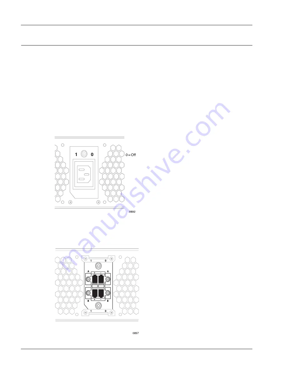
You power on the SmartEdge 100 router by moving the on-off toggle switch (circuit breaker) on the chassis
rear panel to the ON position, which is marked by a stamped “1” on the chassis rear panel. You power it off
by moving the switch to the OFF position, which is marked by a stamped “0”. The AC version of the
SmartEdge 100 chassis has a single circuit breaker above the AC power cord connector; see Figure 5-1.
The DC version of the chassis has dual circuit breakers with the A-side switch above the A-side connector
and the B-side switch below the B-side connector; see Figure 5-2.
The circuit breaker provides protection against power surges and drops; if a power surge or drop occurs that
is outside the range of power supported by the system, the circuit breaker shuts down the system. Electrical
specifications are included in the “Electrical Specifications” section in Chapter 3, “Preparing for
Installation.”
Figure 5-1
AC Chassis Circuit Breaker
Figure 5-2
DC Circuit Breakers
Summary of Contents for SmartEdge 100
Page 4: ......
Page 8: ...viii SmartEdge 100 Router Hardware Guide...
Page 14: ...Ordering Documentation xiv SmartEdge 100 Router Hardware Guide...
Page 52: ...Connecting and Routing the Cables 4 18 SmartEdge 100 Router Hardware Guide...
Page 72: ...Obtaining Assistance 5 20 SmartEdge 100 Router Hardware Guide...
Page 90: ...FE and GE MIC and Native Port Cables A 6 SmartEdge 100 Router Hardware Guide...
Page 94: ...FE and GE Port Alarms B 4 SmartEdge 100 Router Hardware Guide...