background image

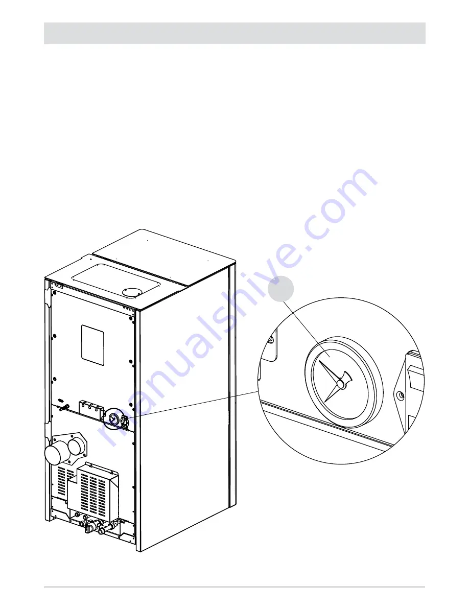
m

34

6-HYDRAULIC CONNECTION

PRESSURE GAUGE

The gauge of the boiler “m” is one of the key tools, which is used to check that appliance is operating smoothly. The pressure gauge of the 

boiler is used to measure the pressure, i.e. the difference between the internal pressure and the atmospheric pressure. Generally, the ideal 

pressure for a boiler is between 1.5 and 2 bar, above or below which malfunctions occur in the heating system or in the supply of domestic 

hot water. The pressure adjustments are made through the vent valve “G” at the top of the boiler (see instructions on the previous page).

Low boiler pressure

When the pressure of the boiler is too low, and therefore it is indicated on the pressure gauge as below 1.5 bar, the heating does not work 

well, hot water does not arrive or the boiler is blocked. The main reasons that lower the pressure are:

•  Temperature too low, which causes the condensation to form

•  Air in the pipes

•  A fault in the 3-way valve

High boiler pressure

If the pressure is high, that is the boiler pressure gauge marks more than 2 bar, the energy efficiency of the boiler decreased, which means 

that the consumption increases.

Summary of Contents for PERFORMA 25

Page 1: ...INSTALLATION GUIDE EN PELLET BOILER PERFORMA 25 PERFORMA 30 PART 1 REGULATIONS AND ASSEMBLY Instructions in English...

Page 2: ...I INTRODUCTION 1 1 WARNINGS AND WARRANTY CONDITIONS 2 2 INSTALLATION 9 3 DRAWINGS AND TECHNICAL FEATURES 19 4 INSTALLATION AND ASSEMBLY 22 5 REMOVING THE AESTHETICS 25 6 HYDRAULIC CONNECTION 29 7 ELEC...

Page 3: ...nder the ownership of RED No part of this manual may be translated into other languages adapted or reproduced even in part in other mechanical or electronic forms photocopies recordings or other witho...

Page 4: ...ensory or mental capabilities or lack of experience and knowledge if they have been given supervision or instruction concerning use of the appliance in a safe way and understand the hazards involved C...

Page 5: ...nerateanabnormalamountofunburnedgas witha risk of explosion in the chamber Accumulated unburnt pellets in the burner after a failed ignitions must be removed before lighting Failure to clean and maint...

Page 6: ...de of flammable materials In the event of a malfunction of the ignition system do not force it to light by using flammable materials Special maintenance must only be performed by authorised and qualif...

Page 7: ...f 2 two years from the date of purchase as proved by a document to serve as proof of purchase invoice and or receipt that shows the name of the vendor and the date on which the purchase was made forwa...

Page 8: ...he annual boiler maintenance performed by an authorised technician or qualified personnel will result in the loss of the warranty Also excluded from this warranty are parts subject to normal wear such...

Page 9: ...horisation Allpartsmustbereplacedwithoriginalspareparts WARNINGS FORTHE CORRECT DISPOSAL OFTHE PRODUCT The owner is the sole party responsible for demolishing and disposing of the product This must be...

Page 10: ...ratorsfuelledbywoodorothersolidbio fuels Test installation controlandmaintenance forthermochemical power at the firebox lower than 35kW UNI TS 11278 general technical regulation for the choice of smok...

Page 11: ...that of pellets is around 4 9 kW kg To ensure good combustion the pellets must be stored in a dry place and protected from dirt Pellets are usually supplied in 15 kg bags therefore storing them is ve...

Page 12: ...rniture andwithgoodaircirculation to allow effective ventilation for the appliance The product should be located in an area that allows sufficient space for normal use and maintenance operations The v...

Page 13: ...g requirements Increase the cross section by at least 6 cm2 for each 1 kW 859 64kcal h The minimum cross section of the opening must not however measure less than 100 cm2 The cross section can be calc...

Page 14: ...ormance have cooler fumes with consequently weaker draft and the possible formation of condensation It is therefore essential that the flue meets all construction standards and is always maintained in...

Page 15: ...on the data tags of the flue in accordance with EN1856 1 EN1443 the safety distances that must be respected in presence of passing combustible materials and the type of insulating material to be used...

Page 16: ...20 metres D 0 50 metres ABOVE HIGHEST POINT E 2 10 metres F REFLUX AREA A MIN 2 00 metres B DISTANCE 1 30 metres C DISTANCE 1 30 metres D 0 50 metres ABOVE HIGHEST POINT E 1 50 metres F REFLUX AREA FI...

Page 17: ...shown in the technical data tables are indications for correct installation Any alternative configurations must be correctly sized in accordance with the general method of calculation of UNI EN13384 1...

Page 18: ...afety CHIMNEYPOT Thechimneypotisacrucialelementfortheheatingappliancetoworkproperly werecommendawindproofchimneypot A seeFigure7 The area of the opening for smoke extraction must be at least double th...

Page 19: ...t can withstand the high operating temperatures of the appliance min T200 class P1 The use of flexible metal hoses made of fibre cement or aluminium is forbidden For direction changes we always recomm...

Page 20: ...m safety distances from combustible materials The previous rules also apply for holes made in walls 2 Oldflue minimumtube 150mmwiththeinclusionof an external access door for chimney cleaning 3 Externa...

Page 21: ...743 605 1321 429 393 109 486 80 100 19 3 DRAWINGS ANDTECHNICAL FEATURES Technical Dept All rights reserved Reproduction is prohibited DRAWINGS AND CHARACTERISTICS PERFORMA 25 30 BOILER DIMENSIONS...

Page 22: ...Pa 0 10 mbar 10 Pa Recommended draught at Min power 0 05 mbar 5 Pa 0 05 mbar 5 Pa Smoke mass 15 6 g sec 18 3 g sec Tank capacity 100 litres 100 litres Type of pellet fuel Pellet diameter 6 8 mm and s...

Page 23: ...0 140 160 180 200 220 240 260 280 300 320 340 360 380 400 420 440 460 480 0 50 100 150 200 250 300 350 400 450 500 550 600 650 700 750 800 850 900 950 1000 1050 1100 B FLOW RATE dm3 h A PRESSURE HEAD...

Page 24: ...the boiler to the pallet as well as the x and y screws There are two S fixing brackets one at the front and one at the back Install the boiler in the area set aside for it making sure it conforms to...

Page 25: ...in force Position the product and proceed with connecting it to the chimney If the product must be connected to an exhaust pipe that goes through the rear wall to enter the chimney make sure not to fo...

Page 26: ...clearance in front of the product for the purpose of cleaning maintenance etc must be 1000 mm the minimum permissible distance between the back of the product and a wall must be 500 mm the minimum di...

Page 27: ...e components of the boiler or if you are just cleaning it you need to remove the side panels To remove the right panel D proceed as follows lift the tank cover C lift the front cover B open the decora...

Page 28: ...k D 26 5 REMOVINGTHE AESTHETICS...

Page 29: ...GTHE AESTHETICS Technical Dept All rights reserved Reproduction is prohibited REMOVINGTHE LEFT SIDE PANEL Remove the left side panel E by following the instructions for the right side panel Unlike pan...

Page 30: ...g so as to prevent the pellet from falling on the door REAR COVER FORTHE HYDRAULIC KIT The back of the boiler has a removable cover to insert the selected hydraulic kit Remove cover R by loosening the...

Page 31: ...CONNECTINGTHEBOILER INORDERTOREMOVEALLRESIDUEANDDEPOSITS Upstream from the boiler always install shutters so as to disconnect it from the plumbing system should it be necessarytomoveit orwhenitrequire...

Page 32: ...2 6 7 30 6 HYDRAULIC CONNECTION CONNECTION DIAGRAMWITH HYDRAULIC KIT FOR DHW PRODUCTION SEE ACCESSORY CODE 40A16003 2 SAFETYVALVE 5 DOMESTICWATER INLET 3 FILLINGTAP 6 HEATING RETURN 4 DOMESTICWATER O...

Page 33: ...hydraulic kit The safety valve drain must be connected to a rubber pipe that can withstand a temperature of 110 C not supplied and that reaches the outside via an anti odour syphon This drain is provi...

Page 34: ...be the same In open vessel heating systems direct contact between circulating liquid and air is allowed During the heating season the user must check the circulating water level in the expansion tank...

Page 35: ...lf NOTE In systems with a closed vessel where possible the water pressure in the heating system must not be lower than 1 barwhenthesystemisatroomtemperature ifthisisnotthecase usethetaptofillthesystem...

Page 36: ...e pressure adjustments are made through the vent valve G at the top of the boiler see instructions on the previous page Low boiler pressure Whenthepressureoftheboileristoolow andthereforeitisindicated...

Page 37: ...on the electrical cables do not expose the appliance to the elements rain sun etc do not allow children or inexperienced persons to use the appliance Connection to 230V power supply The installation o...

Page 38: ...llet boilers It is good practice to guarantee effective ventilation in the room during the initial start up as the boiler will emit somesmokeandsmellofpaint ATTENTION Please ensure the brazier is clea...

Page 39: ...penedwiththeboilercoilandoff Ifthedoorsareopenedwhiletheboilerisrunning asystemwilltriggerthealarmandtheboilerwillgooff Open the outer door A by grasping the handle at the top right and pull towards y...

Page 40: ...oiler directly and pour in the pellets Automatic loading with remote tank of 200 400 or 300 kg optional see accessories Remove the round V plate from the door by removing the two u screws and disconne...

Page 41: ...afely What to do in the event of failed ignitions What to do in the event of alarms in particular those generated when the appliance runs out of fuel How to maintain the appliance correctly and the im...

Page 42: ......

Page 43: ......

Page 44: ...REV 0 8901624100 Via La Croce n 8 33074Vigonovo di Fontanafredda PN ITALY Telefono 0434 599599 a s Fax 39 0434 599598 Internet www red fire it e mail info red fire it 21 11 2016...

Reviews: