

CONNECTION AND OPERATION
INSTRUCTIONS
PROTECTION
The device must be installed in accordance with the specifications of EN
60950.
It must be possible to switch off the device using a suitable disconnecting
device outside the power supply. For example, primary side line protection
could be used.
In case of DC applications it is necessary to connect in series an adequate fuse.
RAIL MOUNTING
The power supply unit can be snapped onto all mounting rails in accordance
with EN 50022-35. Installation should be made horizontally (input terminal
blocks below).
CABLE CONNECTION
The device is equipped with COMBICON plug connectors.
This easy-to assemble connection method allows devices to be exchanged
easily and the electrical connection to be visibly isolated.
Connecting Cables:
Cable cross sections from 0.2 to 2.5 mm
2
rigid (solid)/flexible (stranded)
(AWG 24-14) may be used.
To maintain UL, use copper cable rated for an operating temperature of
75°C/170°F.
For Reliable And Touch-proof Contacts:
Strip the connection ends (7 mm - See Figure).
INPUT
The input connection is made by the screw
connections “L(+)” and “N(-)” (torque 0.5 Nm) on the
COMBICON plug connection.
For device protection, there is an internal fuse.
Additional device protection is not necessary.
Recommended backup fuses are power circuit-
breakers 6 A or 10 A, charactistic B (or identical
function). In DC applications, a suitable backup fuse
must be wired in.
If the internal fuse is triggered, there is most
probably a malfunction in the device. In this
case, the device must be inspected in the
factory
!
OUTPUT
The 24 VDC connection is made by the screw connections “+” and
“-” (torque 0.5 Nm) on the COMBICON plug connection. At the time of
delivery, the output voltage is 24 VDC. The output voltage can be set from 22.5
to 28.5 VDC on the potentiometer.
The device is electronically protected against short circuits and idling. In the
event of an error, the output voltage is limited to max 35 VDC.
Function Monitoring
For function monitoring, there is the active DC OK switching output and the
DC OK LED.
The 24 VDC signal is measured between the “DC OK” and “-” connection
terminal blocks and can be loaded with 20 mA maximum. This signal output
indicates that the output voltage has fallen below 21.5 VDC when “active high”
changes to “low”.
The DC OK signal is isolated from the power output.
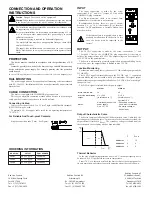
Output Characteristic Curve
The device functions following the U-I characteristic curve. Under load, the
operating point follows this curve. In the event of a short circuit or overload, the
output current is limited to I
BOOST
. The secondary voltage is reduced until the
short circuit on the secondary side has been remedied.
Thermal Behavior
In the case of ambient temperatures above +60ºC, the output capacity has to
be reduced by 2.5% per Kelvin increase in temperature.
From +70°C or a thermal overload, the device reduces the output power for
its own protection, and returns to normal operation when it has cooled down.
Caution
: Danger! Never work on live equipment!
Caution
: When the device is opened, a dangerous voltage may remain
at the electrolytic capacitors for up to 2 minutes after shutdown!
The installation must be performed by a specialist in accordance with
the requirements of EN 60950.
For vertical installations we recommend a minimum spacing of 5 cm
(1.97 in.) between other modules and this power supply to ensure
sufficient convection.
No minimum spacing is required for horizontal alignment.
The mains feed line must have an appropriate fixing or strain relief
outside of the device.
The supply-side installation and the connection via screw terminal
blocks must be done in a way that ensures protection against electric
shock.
ORDERING INFORMATION
STATUS 1
STATUS 2
Green LED “ DC OK”
on
off
Active DC OK switching
output
U = +24 V
(in reference to “-”)
U = 0 V
(in reference to “-”)
Status
Normal operation of the
power supply.
U
OUT
> 21.5 V
U
OUT
< 21.5 V
• Secondary consumer
short-circuit or overload
• No mains voltage or
device faulty
U
[V]
U 24
60°C
40°C
I
I
[A]
OUT
N
I
OUT
BOOST
N
OUTPUT
PSDR1
24 VDC @ 1A
PSDR0100
PSDR2
24 VDC @ 2A
PSDR0200
PSDR4
24 VDC @ 4A
PSDR0400
PART NUMBER
MODEL NO.
1
1.3
PSDR0200
2
4
PSDR0400
4
6
PSDR0100
I
BOOST
I
N
Red Lion Controls
20 Willow Springs Circle
York PA 17406
Tel +1 (717) 767-6511
Fax +1 (717) 764-0839
Red Lion Controls AP
31, Kaki Bukit Road 3,
#06-04/05 TechLink
Singapore 417818
Tel +65 6744-6613
Fax +65 6743-3360
Red Lion Controls BV
Printerweg 10
NL - 3821 AD Amersfoort
Tel +31 (0) 334 723 225
Fax +31 (0) 334 893 793


