THE 1/16 DIN CONTROLLERS
TEMPERATURE/PROCESS
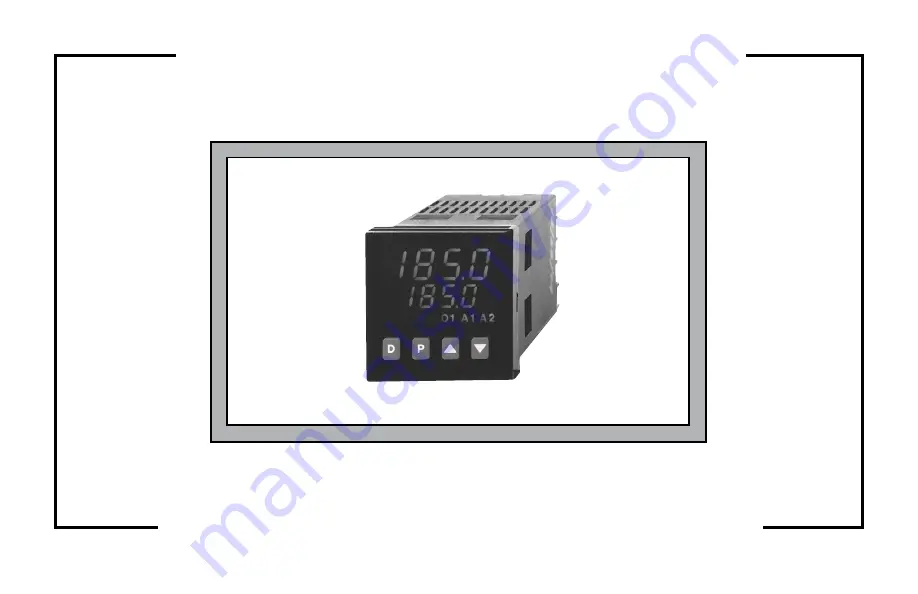
MODELS T48 & P48 INSTRUCTION MANUAL
Page 1: ...THE 1 16 DIN CONTROLLERS TEMPERATURE PROCESS MODELS T48 P48 INSTRUCTION MANUAL ...
Page 2: ...er to adapt to different indication and control requirements The controller which you have purchased has the same high quality workmanship and advanced technological capabilities that have made Red Lion Controls the leader in today s industrial market Red Lion Controls has a complete line of industrial indication and control equipment and we look forward to servicing you now and in the future UL R...
Page 3: ...iring 6 Control and Alarm Outputs 6 Relay Connections 6 Logic SSR Connections T48 only 7 Triac Connections T48 only 7 Heater Current Monitor Wiring T48 only 7 Remote Setpoint Wiring 7 Main Linear DC Output Wiring 7 Second Linear DC Output Wiring 7 User Input Wiring 7 Rear Terminal Assignments 8 T48 Models Without RS 485 and Analog Output 8 T48 Models With RS 485 or Linear DC Analog Output 9 ALL P4...
Page 4: ...1 Configure Module 1 Input Parameters 1 IN P48 22 Configure Module 2 Output Parameters 2 OP 23 Configure Module 3 Lockout Parameters 3 LC 24 Configure Module 4 Alarm Parameters 4 AL 25 Configure Module 5 Cooling Parameters 5 O2 26 Configure Module 6 Serial Communications 6 SC 27 Configure Module 7 Remote Setpoint Parameters 7 rS or 7 n2 28 Configure Module 7 Heater Current Parameters 7 HC or 7 n2 ...
Page 5: ...rtioning Cycle Time CYCt 36 Output Control Action OPAC 36 Output Power Limits OPLO OPHI 36 Sensor Fail Power Level OPFL T48 only 36 Output Power Dampening Filtering Time OPdP 36 ON OFF Control Hysteresis CHYS 37 Auto Tune Code tcod 37 Main Linear DC Output Range ANtP Optional 37 Main Linear DC Output Source ANAS Optional 37 Main Linear DC Update Time ANUt Optional 37 Main Linear DC Output Scaling ...
Page 6: ...eters Module 7 n2 or 7 rS Optional 45 Remote Setpoint Display Values dSP1 and dSP2 45 Remote Setpoint Signal Input Values INP1 and INP2 45 Remote Setpoint Filtering Fltr and bANd 45 Remote Local Setpoint Transfer Options trnF 45 Heater Current Monitor Module 7 N2 or 7 HC Optional 46 Second Linear DC Analog Output Module 8 A2 Optional 46 Second Linear DC Output Range A2tP 46 Second Linear DC Output...
Page 7: ...59 Examples of Command Strings 59 Command Code Explanations 59 Controller Node Address N 59 Read Register Command Code T 60 Write Register Command Code V 60 Reset Alarm Command Code R 60 Control Action Command Code C 60 Block Read Register Command Code P 60 Terminator or 60 Block Read Command Byte Table 61 Unique Register Explanations 62 Setpoint Ramp Using Automatic Setpoint Ramping Register K 62...
Page 8: ...ote Setpoint Input Check T48 and P48 69 Heater Current Input Check T48 only 69 Error Flag E CL 70 Calibration For T48 70 Factory Service Operations Calibration 9 FS 70 Millivolt Calibration CAL 70 Thermocouple Cold Junction Calibration CJC 71 RTD Ohms Calibration rtd 71 Main or Second Linear DC Analog Output Calibration 71 Remote Setpoint Calibration 71 Heater Current Input Calibration 71 Calibrat...
Page 9: ...nge The T48 optional Heater Current Monitor provides a direct readout of process heater current An alarm can be programmed to signal when the heater has failed This provides early warning of system failure before product quality is affected A Remote Setpoint input 0 4 to 20 mA allows for cascade control loops where tighter control quality is required and allows for remotely driven setpoint signal ...
Page 10: ... gasket and discard Slide the panel gasket over the unit from the rear seating it against the lip at the front of the case 4 Insert the unit into the panel cutout While holding the unit in place push the panel latch over the rear of the unit engaging the tabs of the panel latch in the farthest forward slot possible 5 To achieve a proper seal tighten the panel latch screws evenly until the unit is ...
Page 11: ...it through the panel from the rear REMOVING BEZEL ASSEMBLY The bezel assembly shown in Figure 31 must be removed from the case to replace the output board To remove the bezel assembly insert a flat blade screwdriver into the pry slot on either side of the unit Twist the screwdriver handle until the unit is ejected enough to allow removal Caution The bezel assembly contains electronic circuits that...
Page 12: ...ransformers and other noisy components 4 Long cable runs are more susceptible to EMI pickup than short cable runs 5 In extremely high EMI environments the use of external EMI suppression devices such as Ferrite Suppression Cores for signal and control cables is effective The following EMI suppression devices or equivalent are recommended Fair Rite part number 0443167251 Red Lion Controls FCOR0000 ...
Page 13: ...use the same type Paralleling a single thermocouple to more than one controller is not recommended Generally the red wire from the thermocouple is negative and connected to the controller s common RTD T48 When connecting the RTD be certain that the connections are clean and tight refer to Figure 5 for terminal connections RTD sensors have a higher degree of accuracy and stability than thermocouple...
Page 14: ...s Damage to the unit may occur if polarity is reversed CONTROL AND ALARM OUTPUTS For T48 heating cooling and alarms there are up to two types of ON OFF outputs These outputs can be relay or logic for control or alarm purposes Relay outputs can switch user applied AC or DC voltages Logic SSR drive outputs supply power to external SSR power units One Logic SSR Drive output can control up to four SSR...
Page 15: ...eration keep this common isolated from all other controller commons MAIN LINEAR DC OUTPUT WIRING Models with the Linear DC output option provide either a linear 10 V or a linear 20 mA signal The output range is selected by jumpers on the output board See Linear DC Analog Output Jumper Selection page 12 The terminals are 1 and 2 The common of this output is isolated from input common but is not iso...
Page 16: ...2 1 2 3 2 4 5 6 8 13 14 T4811104 T4811114 9 8 9 10 8 11 12 4 5 6 8 T4820000 T4820010 9 8 9 10 8 11 12 4 5 6 8 13 14 T4820003 T4820013 9 8 9 10 8 11 12 4 5 6 8 13 14 T4820004 T4820014 9 8 9 10 8 11 12 3 4 5 4 6 8 T4820200 T4820210 9 8 9 10 8 11 12 3 4 5 4 6 8 13 14 T4820203 T4820213 9 8 9 10 8 11 12 3 4 5 4 6 8 13 14 T4820204 T4820214 9 8 9 10 8 11 12 3 2 4 5 6 8 T4821000 T4821010 9 8 9 10 8 11 12 ...
Page 17: ...116 9 8 9 10 8 11 12 2 1 3 4 5 4 6 8 13 14 T4810107 T4810117 9 8 9 10 8 11 12 3 4 5 4 6 8 2 1 13 14 T4810108 T4810118 9 8 9 10 8 11 12 3 4 5 4 6 8 2 1 13 14 T4810109 T4810119 9 8 9 10 8 11 12 3 2 4 5 6 8 13 14 T4811002 T4811012 9 8 9 10 8 11 12 1 2 3 2 4 5 6 8 13 14 T4811102 T4811112 9 8 9 10 8 11 12 2 1 3 4 5 4 6 8 T4820201 T4820211 9 8 9 10 8 11 12 2 1 3 4 5 4 6 8 13 14 T4820205 T4820215 9 8 9 1...
Page 18: ...001 P4800011 9 8 10 8 11 12 4 5 6 8 P4810000 P4810010 9 8 10 8 11 12 4 5 6 8 13 14 P4810002 P4810012 9 8 10 8 11 12 2 1 3 4 5 4 6 8 P4810101 P4810111 9 8 10 8 11 12 2 1 3 4 5 4 6 8 13 14 P4810105 P4810115 9 8 10 8 11 12 2 1 3 4 5 4 6 8 13 14 P4810107 P4810117 9 8 10 8 11 12 2 1 3 4 5 4 6 8 13 14 P481010A P481011A 9 8 10 8 11 12 1 2 3 2 4 5 6 8 P4811100 P4811110 9 8 10 8 11 12 1 2 3 2 4 5 6 8 13 14...
Page 19: ...ilding A communication line is run to an industrial computer located in the production office Each controller is programmed for a different address and all are programmed for the same baud rate and parity as the computer ex 9600 baud parity even An application program is written by the user to send and receive data from the units using the proper commands 11 Figure 10 Connecting to a Host Terminal...
Page 20: ...guration in Linear Output Range ANAS in the Output Parameter Module 2 OP The optional secondary set of jumpers must correspond with the configuration in Second Linear DC Output Range A2tP in the Second Linear DC Analog Output Module 8 A2 The jumpers are accessible from the rear after removing the controller from the case Dashed lines show factory setting of 20 mA 12 Figure 11 Linear Output Range J...
Page 21: ...the annunciators Four front panel buttons are used to access different modes and parameters The following is a description of each button Do NOT use tools of any kind screwdrivers pens pencils etc to operate the keypad of this unit BUTTON FUNCTIONS D In the Normal Display Mode the Display D button is used to select one of the operational parameters in the secondary display In other modes pressing ...
Page 22: ...s are used to change the desired parameter value and the P button enters the new value and moves to the next parameter The Setpoint value lower display is changed with the Up or Down arrow buttons when it is selected in the Normal Display Mode PARAMETER CONFIGURATION BASIC START UP For basic start up it is important to verify or change Input Parameter Module 1 IN parameters tYPE and SCAL and Outpu...
Page 23: ...L MODES O1 MODE O2 MODE MANUAL CONTROL OUTPUT POWER RANGE O1 STATE O2 STATE PID 0 to 100 O1 TP ON OFF ProP 0 0 100 O1 ON Any other setting O1 OFF PID PID 100 to 100 O1 TP O2 TP PID ON OFF GAN2 0 0 0 to 100 O1 TP O2 OFF 100 to 0 O1 TP O2 ON ON OFF ProP 0 0 ON OFF GAN2 0 0 100 O1 ON O2 OFF 100 O1 OFF O2 ON Any other setting O1 OFF O2 OFF TP Time Proportioning 15 ...
Page 24: ...FRONT PANEL PROGRAMMING CHART FOR T48 P48 CONTROLLERS 16 ...
Page 25: ... Not limited by OPLO OPHI in 2 OP DV Setpoint Deviation 999 to 9999 Read only Shows difference between Temp Process top display and Setpoint DV Heater Current 999 to 9999 Read only Heater Current models show heater current value and not process deviation Units Symbol F or C Read only T48 models only Blank Blank display P48 models only FRONT PANEL PROGRAM DISABLE There are several ways to limit the...
Page 26: ...ormal Display Mode if no action is taken Unprotected Parameter Mode Reference Table Display Parameter Range and Units Factory Setting Description Comments SP Local Setpoint SP1 or SP2 999 to 9999 0 T48 0 0 P48 Range limited by SPLO SPHI User Input or Hidden Function Mode selects SP1 or SP2 OPOF Output Power Offset 99 9 to 100 0 0 0 Appears only if Intt 0 and unit is in Automatic Control OP Output ...
Page 27: ...ogrammed for PLOC continue to CodE and press the arrow buttons until the value equals the Code as entered in parameter lockouts When an incorrect code value is entered or when the D button is pressed End will momentarily appear and the controller will return to the Normal Display Mode Protected Parameter Mode Reference Table Display Parameter Range and Units Factory Setting Description Comments Pr...
Page 28: ...er Mode is accessed by pressing the Up button from CnFP in the Unprotected Parameter Mode While in this mode the various Configuration Modules can be displayed by pressing the Up or Down buttons The process value after initial setup will be displayed in the main top display The Configuration Module will appear alternating with CnFP in the secondary bottom display To access a Configuration Module p...
Page 29: ... msec display update rate Adjusted by Auto Tune Display Parameter Range and Units Factory Setting Description Comments SHFt Input Signal Shift correction offset 999 to 9999 1 or 0 1 degree 0 Normally set to 0 SPLO Setpoint Lower Limit 999 to 9999 0 or 0 1 degree 0 Set low limit below high limit SPHI Setpoint Upper Limit 999 to 9999 1 or 0 1 degree 9999 Set high limit above low limit SPrP Setpoint ...
Page 30: ...e dSP2 Scaling Point 2 Display Value 999 to 9999 100 0 Key in display high value Display Parameter Range and Units Factory Setting Description Comments InP2 Scaling Point 2 Input Signal 0 4 20 mA DC 0 10 VDC 0 00 to 20 00 mA 0 00 to 10 00 V 20 00 Press D button to select Signal Input method Value Key in Method Key in input low value Signal Input Method Apply input low value SPLO Setpoint Lower Lim...
Page 31: ...he event of input sensor failure T48 only 100 to 100 O1 O2 0 OPdP Output Power Dampening filtering Time 0 to 250 seconds 3 T48 1 P48 0 off no dampening Set in range of 1 50 to 1 10 of integral time Adjusted by Auto Tune Display Parameter Range and Units Factory Setting Description Comments CHYS ON OFF Control Hysteresis 1 to 250 2 T48 0 2 P48 For O1 ON OFF Control Change to Factory Setting prior t...
Page 32: ... indicator Illuminates when selected UdSP Units display access For T48 LOC lockout rEd read only rEd Determines display of F or C bdSP Blank display access For P48 LOC lockout rEd read only rEd Determines blank secondary display CodE Access code 0 to 250 0 Refer to front panel disable section for access levels Display Parameter Range and Units Factory Setting Description Comments PId PID values ac...
Page 33: ...e 999 to 9999 0 T48 0 0 P48 If band alarm action then only a positive value can be entered ACt2 Alarm 2 action mode A HI absolute high A LO absolute low d HI deviation high d LO deviation low b IN band inside b ot band outside CooL cooling output Hcur heater current alarm A HI If changed check alarm values If cooling is selected the remaining Alarm 2 parameters do not appear For P48 cool is second...
Page 34: ...r Range and Units Factory Setting Description Comments CYC2 Cooling output cycle time 0 to 250 sec 2 0 turns O2 off GAN2 Relative cooling gain 0 0 to 10 0 1 0 0 0 places cooling output into ON OFF Control and db 2 becomes hysteresis value db 2 Heating or cooling overlap deadband 999 to 9999 0 Positive value is deadband Negative value is overlap If GAN2 0 this parameter is cooling ON OFF Control hy...
Page 35: ...ue node address Abrv Abbreviated or full transmission yes no no Selecting yes the controller does not transmit mnemonics PoPt Print options yes no no Selecting yes allows print options shown below to be programmed INP Input yes no yes SEt Setpoint yes no yes OPr Output Power yes no yes Pbd Proportional Band yes no no INt Integral Time yes no no Display Parameter Range and Units Factory Setting Des...
Page 36: ...o configuration access point CnFP NO if heater current option is not installed Display Parameter Range and Units Factory Setting Description Comments Hcur Heater current transformer scaling 0 0 to 999 9 Amps 40 0 Set scaling equal to primary rating of CT Configure Module 8 Second Linear DC Analog Output 8 A2 Controller returns to Configuration Access Point CnFP NO if second linear DC analog option...
Page 37: ...MNEMONIC PARAMETER USER SETTING tYPE Input Type dCPt Decimal Point rnd Rounding Increment FLtr Digital Filtering dSP1 Display Value 1 InP1 Signal Input Value 1 dSP2 Display Value 2 InP2 Signal Input Value 2 SPLO Setpoint Lower Limit SPHI Setpoint Upper Limit SPrP Setpoint Ramp Rate InPt User Input CONFIGURE OUTPUT 2 OP MNEMONIC PARAMETER USER SETTING CYCt Cycle Time OPAC Output Control Action OPLO...
Page 38: ...e GAN2 Relative Cooling Gain db 2 Heat Cool Overlap Deadband CONFIGURE SERIAL COMMUNICATIONS 6 SC MNEMONIC PARAMETER USER SETTING bAUd Baud Rate ConF Character Frame Format Addr Controller Address Abrv Abbrev or Full Transmission PoPt Print Options INP dEv SEt OFP OPr r_P Pbd Crg Int Cdb dEr OSt AL1 RSP AL2 HCr CONFIGURE REMOTE SETPOINT 7 rS 7 n2 MNEMONIC PARAMETER USER SETTING dSP1 Remote Setpoin...
Page 39: ...lue Additionally with large derivative times control action may be too unstable for accurate control Increase the filter value Conversely if the fastest controller response is desired decrease the filter value The Auto tune procedure sets the filter value appropriate to the process characteristics Also see Output Power Dampening parameter OPdP page 36 for filtering the output Fltr 0 to 4 0 least i...
Page 40: ...nctions The input must be in its active state for 120 msec minimum to perform the function A function is performed when the User Input Terminal 6 is pulled low to common Terminal 8 Note Do not tie the commons of multiple units to a single switch Use either a multiple pole switch for ganged operation or a single switch for each unit Note Low Level is switch closed High Level is switch open PLOC Pro...
Page 41: ...curacy of the unit Digital Input Filtering and Display Update Rate FLtr Select the relative degree of input signal filtering and display update rate The filter is an adaptive digital filter that discriminates between measurement noise and actual process changes Therefore the influence on step response time is minimal If the signal is varying too greatly due to measurement noise increase the filter...
Page 42: ... indicates the signal value applied to the input terminals The unit can be toggled to the key in method by pressing the D button again Signal Range Display Range 4 00 to 20 0 mA DC 0 00 to 20 00 0 00 to 10 00 VDC 0 00 to 10 00 When the desired value is indicated on the display press the P button to store the value and advance to the next parameter Setpoint Limit Values SPLO SPHI The controller has...
Page 43: ...ow Level is switch closed High Level is switch open PLOC Program Lock A low level enables the program disable function which places the unit in the Protected Parameter Mode ILOC Integral Action Lock A low level disables the integral action of the PID computation A high level resumes the integral action trnF Auto Manual Transfer A negative transition places the unit in the manual user mode and a po...
Page 44: ...than 0 to limit maximum cooling or set to greater than 0 to limit minimum heating Set the High Limit to less than 0 to limit minimum cooling or greater than 0 to limit maximum heating When controlling power in the manual control mode the output power limits do not take effect Sensor Fail Power Level OPFL T48 only If a failed sensor is detected the control output s default to a preset power output ...
Page 45: ...nge selected See Linear DC Output Jumper Selection page 12 The linear DC output can be re calibrated to provide up to 5 of over range operation See Main or Second Linear DC Analog Output Calibration page 71 Main Linear DC Output Source ANAS Optional The output can be programmed to transmit one of the below variables OP Output Power control INP Temperature retransmission SP Setpoint local or remote...
Page 46: ...ss D once in the Normal Display Mode to remove it from the display Protected Mode Lockouts CodE PId and AL The protected mode is active when program disable is active The parameters in the protected mode can be set for one of the following modes LOC Lockout Prevents the parameter from appearing in the protected mode rEd Read only Parameter appears but cannot be modified Ent Entry Parameter appears...
Page 47: ...cting b In Band Inside Acting b Ot Band Outside Acting b Ot Band Outside Acting Heat Assigns output 01 A1 as control output CooL Assigns 02 A2 as cooling or second output Hcur Assigns A1 as heater break alarm T48 Hcur Assigns A2 as heater break alarm T48 Model Number Dependent Note Deviation and band type alarms track both local and remote setpoint Heater Break Alarm T48 models equipped with the H...
Page 48: ... and the front panel indicator for various over under temperature conditions The alarm output wave form is shown with the output in the automatic reset mode Note Select the alarm action with care In some configurations the front panel indicator LED might be OFF while the output is ON 40 ...
Page 49: ... 41 ...
Page 50: ...d alarms when the setpoint is changed via keypad This action suppresses nuisance alarms Figure 18 Alarm Standby Delay Sequence depicts a typical operation sequence Alarm Value AL 1 AL 2 The alarm values are either absolute absolute alarms or relative to the setpoint value deviation and band alarms An absolute alarm value is the value that is entered A relative alarm value is offset from the temper...
Page 51: ... OFF Control Hysteresis CHYS in Output Parameter Module 2 OP becoming the cooling output hysteresis This may be done independent of the main output control mode PID or ON OFF Relative gain is generally set to balance the effects of cooling to that of heating for best control Figures 19 20 21 Heat Cool Operation illustrate the effect of different gains GAN2 0 0 to 10 0 Heat and Cool Overlap Deadban...
Page 52: ...and when communicating with the controller The address numbers range from 0 to 99 Abbreviated or Full Transmission Abrv When transmitting data the controller can be programmed to suppress the address number mnemonics units and some spaces by selecting YES An example of abbreviated and full transmission are shown below NO 6 SET 123 8F CR LF Full Transmission YES 123 8 CR LF Abbreviated Transmission...
Page 53: ...long as the difference between the current reading and the previous reading is less than the filter band value band the filter remains in effect When the difference exceeds the filter band the filter disengages until the difference is less than the filter band value This action allows quick filter response to large setpoint changes while retaining filtering action under normal process conditions N...
Page 54: ...e 0 10 0 to 10 V 0 20 0 to 20 mA 0 40 4 to 20 mA The linear DC output range jumper must be set to match the range selected See Linear DC Output Jumper Selection page 12 The linear DC output can be re calibrated to provide up to 5 of over range operation See Linear DC Output Calibration page 71 for more details Second Linear DC Output Scaling Points A2LO A2Hl The output can be scaled based on the c...
Page 55: ...e with the P and MN annunciators illuminated In Time Proportional output control relay logic or triac the percent output power is converted into output on time using Time Proportioning Cycle Time CYCt value in Output Parameter Module 2 OP For example with 4 cycle time and 75 power the output will be on 4 x 75 for 3 seconds and off for 1 second In Linear DC output control 0 10 VDC or 0 4 20 mA the ...
Page 56: ...arameter Module 2 OP can be set to reverse rEv for heating output on when below the setpoint or direct drct for cooling output on when above the setpoint applications In controllers with operating system software revision earlier than V4 x the ON OFF Control Hysteresis value is not balanced around the setpoint value In these controllers the Hysteresis is totally added to the setpoint in reverse ac...
Page 57: ...ations the Control Action OPAC in Output Parameter Module 2 OP is normally set to reverse rEv This sets O1 into reverse heat with O2 always in direct cool Cooling output for the P48 is referred to as the second control output In controllers with operating system software revision lower than 4 0 the ON OFF Control Hysteresis value is not balanced In these controllers the Hysteresis is totally added...
Page 58: ... 50 Figure 26 O1 O2 ON OFF Control Software Revision V4 0 or Later Figure 27 O1 O2 ON OFF Control Software Revisions V3 x or Earlier ...
Page 59: ...Tune requires the hysteresis setting to be above the process noise floor generally 2 5 degrees or 1 2 of range is adequate For most applications the control hysteresis should be set at 2 factory setting The Auto Tune code may be set to yield the response characteristics shown in Figure 28 Auto Tune Code A code setting of zero gives the fastest response with possible overshoot and a code of two giv...
Page 60: ...meter to 0 0 prior to starting Auto Tune After the completion of Auto Tune this parameter may need to be reset It is important that external load disturbances be minimized and if present other zone controllers idled as these may have an effect on the PID constant determination The controller additionally sets the Cooling Relative Gain parameter GAN2 for heat cool systems Some water cooled processe...
Page 61: ...ntegral time is defined as the time in seconds in which the output due to integral action alone equals the output due to proportional action with a constant process error As long as a constant error exists integral action repeats the proportional action each integral time Integral action shifts the center point position of the proportional band to eliminate error in the steady state The units of i...
Page 62: ...ntegral times to maintain the same degree of stability as with derivative action Derivative action is disabled by setting the time to zero Output Power Offset Manual Reset If the integral time is set to zero automatic reset is off it may be necessary to modify the output power to eliminate errors in the steady state The output power offset OPOF is used to shift the proportional band to compensate ...
Page 63: ...PID Adjustments Cont d 55 Figure 34 Process Response Extremes ...
Page 64: ...ol and set Power from the Normal Display Mode to drive the process value to the desired value Make certain that the controller can drive the process to the setpoint Allow the process to stabilize after setting the Power 6 Place controller into Automatic Control If the process will not stabilize and starts to oscillate set the Proportional Band 2x higher and go back to step 5 7 If the process is st...
Page 65: ...less than the filter band value keep the filter engaged while fluctuations outside the filter band disable the filter This action allows the controller to respond rapidly to large changes of the remote setpoint signal CASCADE CONTROL External cascade control involves the use of two controllers one of which has a Remote Setpoint Input The outer loop controller Primary controller directs the setpoin...
Page 66: ... length depending on the nature of the command At most a command string consists of a Controller Node Address number not required for address of 0 a Command Code character a Register Identification character for most commands Numerical Data if writing data to the controller and ending with a string Terminator of or The controller will not respond with an error message to invalid commands Sending N...
Page 67: ... 100 msec setpoint not saved to E2 PROM Examples of Command Strings Example Write 10 0 to Setpoint register with a controller address of 2 Command String N2VB100 Explanation Address 2 Command V Register ID B Numeric Data 100 Terminator with setpoint will not be saved to E2 PROM Example Read input register of controller with an address of 3 Command String N3TA Explanation Address 3 Command T Regist...
Page 68: ...ller responds with register data that is preset by the Print Options parameter Module 6 SC This mode is useful for print ticket applications However if Register ID characters follow this command the controller responds with register data indicated by the ID character field This character ID field does not follow the normal Register ID format but instead is a field composed of ASCII encoded bit map...
Page 69: ...me Derivative Time Alarm 1 Alarm 2 ASCII HEX X 1 31 X 2 32 X X 3 33 X 4 34 X X 5 35 X X 6 36 X X X 7 37 X 8 38 X X 9 39 X X A 41 X X X B 42 X X C 43 X X X D 44 X X X E 45 X X X X F 46 Byte3 Deviation Offset Power Setpoint Ramp Cooling Gain ASCII HEX X 1 31 X 2 32 X X 3 33 X 4 34 X X 5 35 X X 6 36 X X X 7 37 X 8 38 X X 9 39 X X A 41 X X X B 42 X X C 43 X X X D 44 X X X E 45 X X X X F 46 Byte4 Cooli...
Page 70: ...wer loss the setpoint value written will be lost when using Termination of the setpoint write command with the character instructs the controller to save the value to E2 PROM memory In this case the setpoint value will be recalled after a power loss Heater Current Response HC T48 only The Heater Current register identifies whether the output is on or off at the time it is read This is indicated by...
Page 71: ...coming data and sets the parity bit to odd even or none mark parity for outgoing data Stop Bit The last character transmitted is the stop bit The stop bit provides a single bit period pause to allow the receiver to prepare to re synchronize to the start of new transmission start bit of next byte After the stop bit the receiver continuously looks for the occurrence of the next start bit Command Res...
Page 72: ...nel t3 10 X of characters baud rate The number of response characters varies depending on the setting of the full abbreviated transmissions parameter At the end of t3 the controller is ready to receive the next command The maximum serial throughput of the controller is limited to the sum of t1 t2 and t3 Full Field Controller Transmission Byte Format The first two characters transmitted are the nod...
Page 73: ...If problems are encountered when interfacing the controller s and host device or printer the following check list can be used to help find a solution 1 Check all wiring Proper polarity of all devices on the serial loop must be observed Refer to previous application examples 2 Check the controller s communication format in module 6 SC Make sure all devices on the serial loop are configured with the...
Page 74: ...12 AL 2 12 NO GO light on outside setpoint 12 1 In Configure Input Parameters tYPE tc J Thermocouple type J SCAL F Control and indicate in F dCPt 0 One degree display resolution FLtr 1 Nominal input signal digital filtering SHFt 0 No shift correction necessary SPLO 140 Limit min setpoint temperature to 140 F SPHI 150 Limit max setpoint temperature to 150 F SPrP 0 0 No setpoint ramping InPt PLOC Us...
Page 75: ... desired temperature The Heater Current Monitor option is used for early detection of heater element failure The multi function User Input can be programmed to allow selection of manual operation when connected to common This allows the user to hold the control output of the controller during abnormal process conditions Figure 39 Plastics Extruder Application shows one such zone 67 Figure 39 Plast...
Page 76: ...tage Input dCPt 0 0 Resolution FLtr XX Calculated by Auto Tune dSP1 0 0 Input low value INP1 0 00 Low display value dSP2 10 0 Input high value INP2 150 00 High display value SPLO 40 0 Setpoint low limit SPHI 80 0 Setpoint high limit SPrP 0 0 No ramping INPt PLOC User input program lock 2 OP Configure Output Parameters CYCt 0 Disable O1 output The remaining parameters in this module are set to fact...
Page 77: ...us points over the range 1 0 to 300 0 ohms The tolerance is 0 3 of span 1LSD 4 Calibrate the controller RTD ohms if out of tolerance Voltage Check P48 1 Connect a DC voltage source with an accuracy of 0 1 or better Apply a 0 to 10 V signal to terminals 8 9 2 In Input Module 1 configure input signal InP1 and display value dSP1 to 0 00 Configure input signal InP2 and display value dSP2 to 10 00 3 Co...
Page 78: ...the input sensor type to thermocouple type J tc j Be sure to set input sensor for proper type Note The controller must be restored to normal display mode before any data is stored Factory Service Operations Calibration 9 FS Display Parameter Range Description Comments CodE Enter function code 48 Calibrate instrument CAL Millivolt Calibration yes no Calibration required for both RTD and TC input If...
Page 79: ...nnect one leg of precision resistance accuracy of 0 1 ohm to terminals 9 and 10 together and the other leg to 8 Display Action Description Comments Rtd1 Connect 0 0 ohm jumper wire Wait 10 seconds press P Rtd2 Connect 277 0 ohm Wait 10 seconds press P Main or Second Linear DC Analog Output Calibration 1 Set the Linear DC Output jumper for the range to be calibrated See Linear DC Analog Output Jump...
Page 80: ...nds press P StP2 Apply 2 5 V Wait 10 seconds press P StP3 Apply 5 0 V Wait 10 seconds press P StP4 Apply 7 5 V Wait 10 seconds press P StP5 Apply 10 V Wait 10 seconds press P Connect current calibration source with an accuracy of 0 1 or better StPA Apply 0 mA Wait 10 seconds press P StPB Apply 20 mA Wait 10 seconds press P Main or Second Linear DC Analog Output Calibration 1 Set the Linear DC Outp...
Page 81: ...controller 1 Replace unit E E2 IN DISPLAY 1 Loss of set up parameters due to noise spike 1 Press D to clear then check all set up parameters a Check sensor input and AC line for excessive noise b If fault persists replace unit E CL IN DISPLAY 1 Loss of calibration parameters due to noise spike 1 Press D to clear then check accuracy of controller a Recalibrate controller b Reset calibration paramet...
Page 82: ...o input sensor with a higher temperature range 3 Reduce temperature 4 Check set up parameters ULUL IN UPPER DISPLAY 1 Input is below range of controller 2 Temperature below range of input probe 3 Excessive negative probe temperature 4 Loss of set up parameters 1 Check sensor or input signal level 2 Change to input sensor with a lower bottom range 3 Increase temperature 4 Check set up parameters SH...
Page 83: ...g Output Board 1 Remove the bezel assembly See Removing Bezel Assembly page 3 2 Lift up on the top bezel board latch while gently pulling out on the bezel display board assembly Do NOT remove the display board from the bezel 3 Remove the output board by pulling it away from the other boards Replace the output board by aligning the board to board connector Be certain the connector is fully mated 4 ...
Page 84: ...ut is active A1 Alarm 1 is active for AL1 Option A2 Alarm 2 is active OR Cooling Second output O2 is active 2 POWER AC Versions 85 VAC min to 250 VAC max 50 to 60 Hz 8 VA max DC Versions DC Power 18 to 36 VDC 7 W AC Power 24 VAC 10 50 to 60 Hz 9 VA 3 CONTROLS Four front panel push buttons for modification and setup of controller functions and one external user input for parameter lockout or other ...
Page 85: ... 00 no standard no standard 8 RTD INPUT T48 only 2 or 3 wire 100 W platinum alpha 0 00385 DIN 43760 alpha 0 0039162 Excitation 150 mA typical Resolution 1 or 0 1 degree Lead Resistance 15W max per input lead RTD TYPE RANGE 385 200 to 600 C 328 to 1100 F 392 200 to 600 C 328 to 1100 F OHMS 1 0 to 320 0 9 P48 RANGE AND ACCURACY Input Range Accuracy 18 to 28 C Accuracy 0 to 50 C Impedance Max Continu...
Page 86: ...e time Programmable Proportional Gain Adjust Programmable Heat Cool Deadband Overlap Programmable 15 MAIN AND SECOND LINEAR DC OUTPUT optional Self powered active Main Control or Re transmission programmable update rate from 0 1 sec to 250 sec Second Re transmission only fixed update rate of 0 1 sec Output Range Accuracy 18 to 28 C Accuracy 0 to 50 C Compliance Resolution 0 to 10 V 0 10 of FS 1 2 ...
Page 87: ...nalog Outputs Remote Setpoint Input Heater Current Input 50 V working 2300 V for 1 minute All other inputs and outputs with respect to relay contacts 2000 VAC Not isolated between Analog Outputs Remote Setpoint and Heater Current commons 20 CERTIFICATIONS AND COMPLIANCES CE Approved EN 61326 1 Immunity to Industrial Locations Emission CISPR 11 Class A IEC EN 61010 1 RoHS Compliant UL Recognized Co...
Page 88: ... RBD48111 Relay Relay Relay YES T4811114 T4811104 RBD48111 Logic SSR T4820010 T4820000 RBD48200 Logic SSR Relay NA T4821000 RBD48211 Logic SSR Relay Relay T4821110 T4821100 RBD48211 Logic SSR Relay Relay YES T4821113 T4821103 RBD48211 Logic SSR Relay Relay YES T4821114 T4821104 RBD48211 Triac Logic SSR Logic SSR T4832210 T4832200 N A This output is programmable as either Control PID or as an Alarm...
Page 89: ...c SSR Logic SSR YES YES T4820219 T4820209 Logic SSR Relay Relay YES T4821112 T4821102 This output is programmable as either Control PID or as an Alarm This output is jumper and program selectable for either a current or voltage Linear DC output These part numbers are equipped with a second setpoint 1 Replacement Output Board RBD48100 may be used 2 Replacement Output Board RBD48111 may be used T48 ...
Page 90: ... BOARD 18 to 36 VDC 24 VAC 85 to 250 VAC YES P4800011 P4800001 N A Relay P4810010 P4810000 RBD48100 Relay Relay YES P4810111 P4810101 N A Relay Relay YES YES P4810115 P4810105 N A Relay Relay YES YES P4810117 P4810107 N A Relay Relay YES YES P481011A P481010A N A Relay Relay Relay P4811110 P4811100 RBD48111 Relay Relay Relay YES P4811112 P4811102 RBD48111 This output is programmable as either Cont...
Page 91: ...omer shall be responsible for determining that a Product is suitable for Customer s use and that such use complies with any applicable local state or federal law b The Company shall not be liable for a breach of the warranty set forth in paragraph a if i the defect is a result of Customer s failure to store install commission or maintain the Product according to specifications ii Customer alters o...
Page 92: ...ls China Unit 1102 XinMao Plaza Building 9 No 99 Tianzhou Road ShangHai P R China 200223 Tel 86 21 6113 3688 Fax 86 21 6113 3683 Red Lion Controls Europe Softwareweg 9 NL 3821 BN Amersfoort Tel 31 0 334 723 225 Fax 31 0 334 893 793 Red Lion Controls India 201 B 2nd Floor Park Centra Opp 32 Mile Stone Sector 30 Gurgaon 122002 Haryana India Tel 91 984 487 0503 ...