


Installing A Red Jacket Submersible LPG Pump-Motor Unit
LPG Pump-Motor Unit
20
If the discharge head is to be installed (see Figure 5), it must be connected to the piping before installing the
pigtail connector and motor. The discharge head should be sealed with a blank fitting and the conduit pressure
tested with nitrogen to 2000 kPa (290 psi). No leaks are allowed.
If using the existing discharge head, visually inspect the pigtail connector in the discharge head, replace if
damaged. In addition examine the sealing surface of the discharge head - clean if necessary with fine emery paper.
The pigtail connector should be lubricated around its shell with petroleum-based jelly, PTFE lubricant or a suitable
alternative. Assemble the pigtail connector in the discharge head making sure the key in the shell aligns with the
notch in the discharge head.
The supplied o-ring (53.6 x 2.6 mm [2.11 x 0.103 in.]) is to be installed in the groove at the top of the pump if
needed. It should be lubricated with petroleum-based jelly, PTFE lubricant or a suitable alternative.
Verify that the end of the motor coupling extends a minimum of 43 mm (1.7 in.) from the mounting face.
The pump should be carefully positioned to the bottom of the motor by first aligning the pump shaft with the motor
coupling. Secure the pump to the motor by using the cap screws and lock washers supplied with the pump. Using
a torque wrench, the screws should be tightened to 28 - 31 ft-lb. (37.8 - 41.9 N•m) each.
The supplied o-ring (25.4 x 1.8 mm [1.0 x 0.070 in.]) installed in the groove at the top of the motor should be
lubricated with petroleum-based jelly, PTFE lubricant or a suitable alternative.
After fitting the gasket to the top of the motor, the motor should be carefully positioned snug to the discharge head
and secured using the supplied socket screws and lock washers. Using a torque wrench, the screws should be
tightened to 10 - 15 ft-lb. (13.5 - 20.3 N•m) each using a cross pattern.
Test the insulation resistance of each motor lead to the metal junction box. Repair if any reading is less than 2 Meg
ohms.
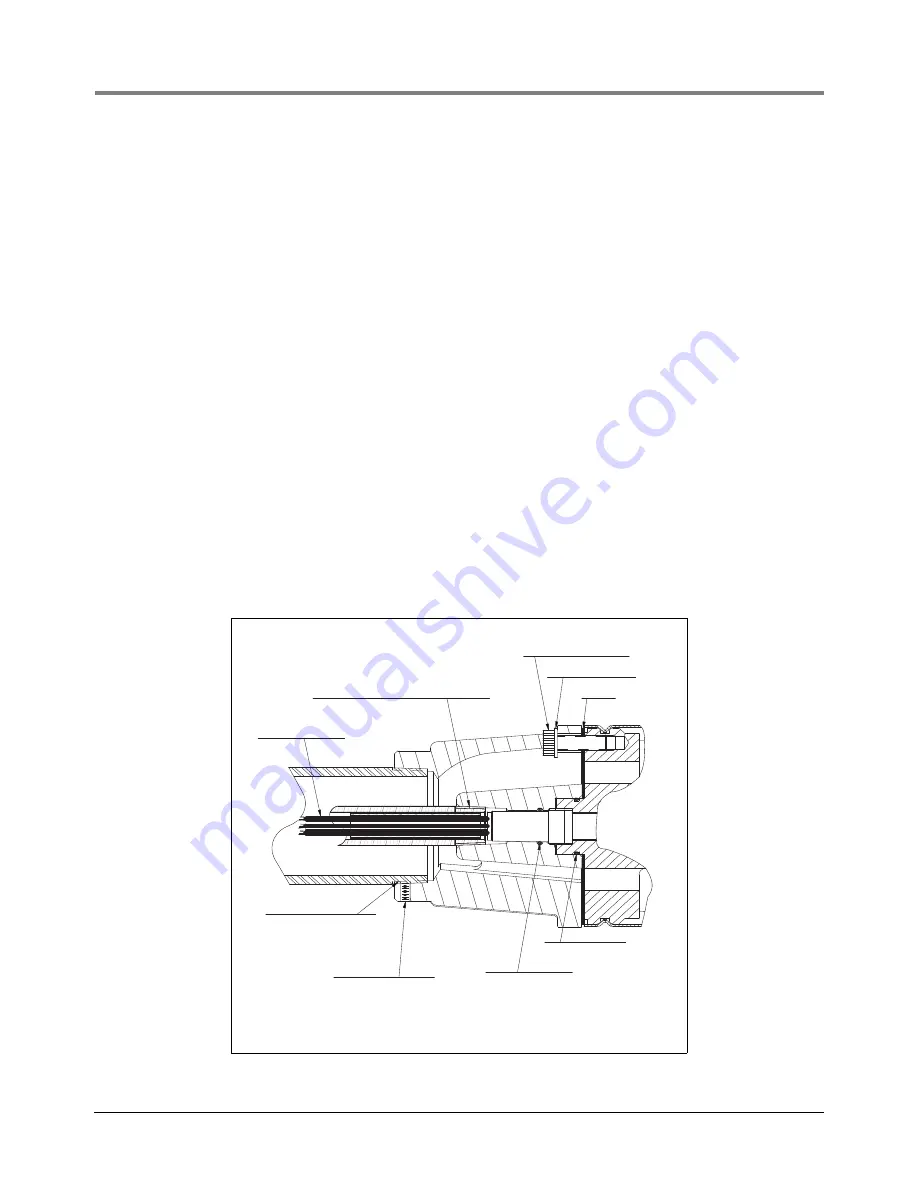
Figure 5. Discharge Head
GASKET
5/16 LOCK WASHER (4)
rj/051-327/fig 3.eps
1/2 Inch - 14 NPTF Schedule 80 Conduit
Supplied By Customer
5 - 7 Thread Engagement (Threads ANSI
B1.20.3, Gaging ANSI B1.20.5) Tighten 34
N• M (25 FT LB). Thread Sealant Required
LPG Resistant Wires
14 AWG 3.0 M (10 FT)
5/16-18 Socket Screw (4)
Tighten 16.9 N•M (12.5 FT LB)
2-Inch NPT Column Pipe
Supplied By Customer
Tighten 165 N•M (120 FT LB)
Thread Sealant Required
1/4-20 Setscrew (2)
Tighten 3.7 N•M (33 IN LB)
Before July 2003
O-Ring 13.9 X 2.62 mm
(.55 X .103 in.)
Since July 2003
O-Ring 14.0 X 1.78 mm
(.55 X .070 in.)
O-Ring 25.4 x 1.8 mm
(1.0 X .070 in.)
Summary of Contents for LPG Premier
Page 38: ......
Page 39: ......
Page 40: ...For technical support sales or other assistance please visit www veeder com...