20
EN
Mounting probe with temperature buffer
It is mandatory to have a galvanic connection between the blue (GND) wire and the earthed con-
tainer (or additional electrode)! With non-metal containers the connection to the BE electrode is
made by means of a direct cable connection to the blue wire of the cable.
The probe can also be installed up-side down.
Electrical version
5-wire DC
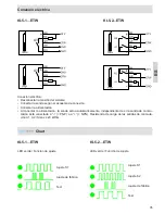
Output function for KFI-5-1...TP...ETW
1 limit value switching point, normally open
Output function for KFI-5-2...TP...ETW
2 limit value switching points, normally open
Operating voltage (U
B
)
15...30 V DC
Permitted residual ripple max.
5 %
Output current max. (I
e
)
100 mA
Power consumption max. (outputs no-load)
0,9 W
Permitted ambient temperature
-25...+70 °C
Permitted ambient temperature (for active zone)
-25 up to +200 °C**
LED-Display
Green
Protective circuit
Built-in
Degree of protection IEC 60529
IP 67
Norm
EN 60947-5-2*
Connection cable
2 m, PVC, 5 x 0,34 mm²
Technical Data
*Where applicable
** For further technical data: See data sheet
BE
KFI-5-1(2)-ETW
≥
15 mm
D
¼D
IB2
M
IB1
1/3D,
min. 50 mm
IB3
Measuring area (M) non-active range 1 (IB1) non-active range 2 (IB2) non-active
range 3 (IB3) area temperature buffer (TP)
Do not mount the measuring range in the area of the container with changes in
the cross section, like the bottom cone of the container
The probe can be mounted in the centre of the container or just off to one side. For a measurement to be independent of the
filling cone, we recommend that the probe be mounted at ¼ of the diameter. The minimum distance between the end of the
measuring range and the container’s lid is 50 mm.
Connect the BE direct to the
blue wire of the cable.
TP


