background image

02

Installation Guide & Function Descriptions 

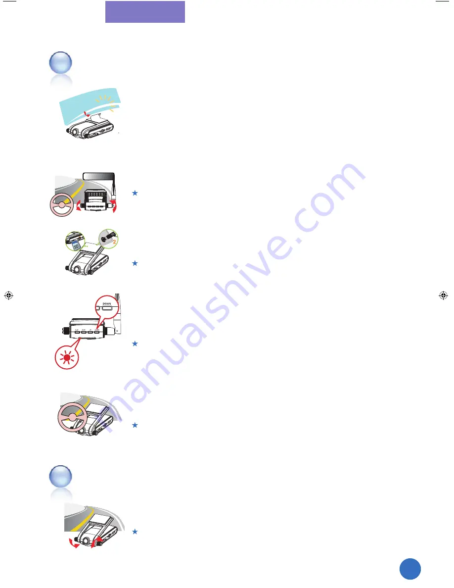
1

 Attach the device

2

 Fix the device

3

 Connect the power

4

 Calibrate G-Sensor 

(Acceleration Sensor)

5


Working Test 

1


Installation


Checkups after installation

17

JS-300G_v3.indd   17

2009-09-10   ¿ÀÈÄ 4:38:53

Get the camera lens focused on the front and fix with Lock Screws of the 

device. 


GPS reception part should be exposed to the window for the better reception. 

Connect the cigar jack to the power port and check if the power is working 

properly. 


SD Card should be inserted before connecting the power. Otherwise, 

Red and Green LED would be blinking at 0.5sec interval by turns. 

Press “Down” for 3 seconds when power is on, and calibrate G-Sensor 

value. (Check if Red LED is blinking at 0.1sec interval rapidly for a second.) 

    When calibrates G-Sensor, put the device on flat place. 

When changes the place to attach the device, calibrating should be done once again. 

Play back the saved data after testing drive. Then, check if the 

data is recorded correctly and revise the camera place on it. 

     JS-300/JS-300G is working based on High- Sensitivity Camera Sensor. 

The recorded video image can be shown dark if the device is installed toward the sky. 

     If the camera angle is not proper, adjust with rotating the lock screw 

and fix it after. 

     Refer to the steps 2 ~ 5. 

Summary of Contents for RVS-300 Black Box

Page 1: ...ection against harmful interference when the equipment is operated in a commercial environment This equipment generates users and can radiate radio frequency energy and if not installed and used in accordance with the instruction manual may cause harmful interference to radio communications Operation of this equipment in a residential area is likely to cause harmful interference in which case the ...

Page 2: ...tions Cautions before installation Installation Guide Mounting Checkups after installation Installation of an external camera Option Function Descriptions Start Event Record Mode Normal Record Mode Full Time Recording Reset GPS Functions Acceleration Sensor G Sensor Calibration G Sensor Data Analysis Example GPRS Functions GPRS Configuration Set 4 8 8 9 10 1 1 12 13 1 6 1 7 1 7 1 8 1 9 1 9 20 20 2...

Page 3: ...key Playback the file recorded on Normal Mode Playback the file recorded on Event Mode Play through PC Viewer Program Installation Codec Installation How to use Viewer Program Playback video file Configuration Set Firmware Update SD Card Data Warranty Policy Warranty 5 26 27 27 28 28 29 30 32 35 36 38 39 40 40 ...

Page 4: ......

Page 5: ...Product Introduction Product Introduction Precautions for Safety Cautions in use Specifications Package Contents Part Descriptions LED Signal Descriptions ...

Page 6: ...g precautions While driving never perform any operation and always park the car in a safe place first before operating the device Do not disassemble repair or reconstruct without an authorized technician Use the device under proper temperature Leaving the device for a long time under hot or cold temperature can be a cause of malfunction Proper Temperature 0 60 Avoid exposing this product to shock ...

Page 7: ...our car The manufacturer does not guarantee about every impacts on your car to trigger this function Prevent any foreign substance to come in contact with the memory card or the internal parts of this device as it might cause malfunctions Keep the lens clean and avoid any obstacles in the camera angle to get the clear view Do not put other substances around the device It can be mirrored through th...

Page 8: ...ution 120 1 3 CMOS 300K Pixel Digital Sensor WDR Support Option 90 CCD 270K Pixel NTSC Internal 3D G Sensor Internal GPS SD Memory Card 1GB 16GB Internal MIC DC 12V 24V From Car Adaptor Upon Impact Automatic Manual Support Support Support 119 5 x 55 0 75 5 x 31 7 mm 137 W O GPRS 157 With GPRS RVS 300 No GPRS RVS 300G GPRS included H 264 VGA 640 480 up to 30fps 2ch use VGA 640x480 up to 15fps 10 ...

Page 9: ...s Actual product specifications may differ from the images in this manual as product enhancements are implemented without prior notice RVS 300 Or RVS 300G External Camera Cable Option 11 GPRS Ant Only for JS 300G Viewer Program CD Cable Tie Holder SD Memory Card A VCable ForTVConnection User Manual CigarJackPowerCable ...

Page 10: ...wer TV Out Jack A V Mode External Camera Video In Jack External Camera Mode External Camera Jack Power RED Event Mode GREEN Normal Mode YELLOW GPRS Only for RVS 300G BLUE GPS Lock Screw Double Faced Foam Tape For attaching to window GPRS Antenna Jack Only for RVS 300G SIM Card Slot Only for RVS 300G 1 A V TV Out 2 External Camera 1 2 3 4 5 6 8 9 10 11 12 13 14 15 7 12 16 16 17 17 RVS 300 ...

Page 11: ...t the same time Light off after lighting Light on continuously Blinking at 1 Sec interval Light on continuously Blinking at 0 1 Sec interval Light on continuously with Orange color Power connecting With SD Card Power Connecting Without SD Card Stand by Event Recording When Event occurs Or when press Emergency Key On Normal Full Time Recording When GPS signal is available When GPS signal is not ava...

Page 12: ......

Page 13: ...fter Installation External Camera Installation Option Function Description Start Event Record Mode Normal Record Mode Full Time Recording Reset GPS Function Acceleration Sensor Calibration G Sensor Data analysis Example GPRS Function Only for JS 300G GPRS Configuration Only for JS 300G ...

Page 14: ...ne before installation Connect the main power of the device at last after installation here in after called Power Insert SD Memory card before connecting the device Install the device in safe and bright place Connect the main power through cigar jack provided DC 12V 24V 16 ...

Page 15: ...Green LED would be blinking at 0 5sec interval by turns Press Down for 3 seconds when power is on and calibrate G Sensor value Check if Red LED is blinking at 0 1sec interval rapidly for a second When calibrates G Sensor put the device on flat place When changes the place to attach the device calibrating should be done once again Play back the saved data after testing drive Then check if the data ...

Page 16: ...allation of the camera External Camera is only for internal use 18 Select a place to install the external camera and fix with the screw provided The connecting part should be toward to the ground Connect the camera to RVS 300 with the cable provided POWER A V Mode Selection Switch must be on CAM to use an external camera After adjusting camera angle fix the camera with the lock screws on the brack...

Page 17: ...ncy Key press until Red LED turns on 2 During Event Record Mode Red LED is blinking at one second second intervals 1 When the impact value recognized by G Sensor acceleration sensor is bigger than user defined value or when user presses Emergency key manually the image and voice before 10 seconds and after 20 seconds of the event will be saved as a file When an event occurs Red LED will be blinkin...

Page 18: ...nal RTC Real Time Clock on GPS time Once set on GPS time it will maintain the exact time without any additional time set The internal RTC time is reflected with connecting the power again after power disconnection 4 If there is any substance which can give the bad effect to GPS reception please leave it in the distance from RVS 300 3 If SD Card storage is full during Normal Mode RVS 300 RVS 300G w...

Page 19: ...er disconnection If a vehicle is parked on a flat plane G Sensor data should have a value of X 0g Y 0g and Z 1g However it would be changed by the place RVS 300 RVS 300G is placed and mounted Thus G Sensor should be calibrated to get more exact data G Sensor Calibration must be done on a flat plane after parking 3 If there is any substance which can give interfere with the GPS reception please lea...

Page 20: ...ta Graph as the below images upon Log Data which is saved with video files and driving status can be analyzed through the graph Stop Acceleration Deceleration Right Turn Left Turn Head On Collision Back Up Collision 1G 0G time Z Y X Z Y X 1G 0G time 1G 0G time 1G 0G time 1G 0G time 1G 0G time 1G 0G time 22 ...

Page 21: ... class 10 3 time slots in RX 43200 bps max and 2 time slot in TX 28800 bps max 4 time slots in RX 57600 bps max and 1 time slot in TX 14400 bps max Yellow LED blinks under GPRS disconnection and it is lighting continuously when GPRS is connected and available to data Tx Rx When GPRS Data is transmitted or received Yellow LED blinks at 0 1 second intervals RVS 300 provides to transmit the below dat...

Page 22: ... Password Authentication Password SMS phone number Type a phone number which SMS is sent to FTP 1 IP Address FTP Server IP Address 2 User ID Authentication User ID 3 Password Authentication Password 4 Port FTP port Send period Set the interval to send Send via Set the protocol which SMS is sent via 1 2 3 1 2 3 4 5 4 5 Click Configuration Setting button on RVS 300 Viewer Program Then click GPRS Tap...

Page 23: ...Playback ...

Page 24: ...Connect a Power Adapter to POWER Adapter is an optional item which may be purchased separately 4 Real Time monitoring of forward shot images 1 Play back the video file saved into SD Card with connecting TV directly Please refer to File Viewer Mode If the power is connected without pressing any key after connecting the A V Cable to TV RVS 300 RVS 300G will start on Forward Shooting Video Output Mod...

Page 25: ... V In the case there are files recorded by CAM 1 and 2 which are mixed up together on Event File Viewer the file recorded by CAM 1 is played first and the file recorded by CAM 2 is played after automatically Function of each key 1 Channel Front Camera 2 Channel External Camera 27 Item PLAY STOP UP DOWN File List Menu Menu Select Playback the selected file Move to top menu Move up Move down On Play...

Page 26: ...1 2 Playback the file recorded on Normal Full Time Mode Select NORMAL FILE VIWER Select Normal File Folder Select the target file to Select EVENT FILE VIWER Select EVENT File Playback the file recorded on Event Mode 28 ...

Page 27: ...ard start image pops up Select the folder to install the program as below image and click Next Select Start Menu folder and press Next button Press Next button when the below image pops up Press Install button to install the program when the below image pops up When the installation is completed the below image pops up Then press Finish button to finish the process ...

Page 28: ...w image pops up 2 Press Next button when the below image pops up 3Press Next button when the below image pops up 4Press Next button when the below image pops up 5 Press Next button when the below image pops up 30 To play back the files recorded through RVS 300 Viewer program K Lite codec provided with a bundle CD must be installed ...

Page 29: ...Installation 6Press Next button when the below image pops up 7Press Next button when the below image pops up 8When the installation is completed the below image pops up Then press Finish button to finish the process 31 ...

Page 30: ...ic part with moving it G Sensor Graph It shows G Sensor data with graphs Menu Button Speedometer and Compass Google Map Users can track the driving route with GPS location data saved with the video file through this map Playback list Indicates the video file route currently played Additional Information Display It shows additional GPS and G Sensor information 1 2 3 4 5 6 7 8 9 1 2 3 4 7 6 5 8 9 32...

Page 31: ...Program Version Information Button and Control It controls the play volume Stop playing and back to the start of the playing file Play the previous file when selects the plural files and views in series Press this key to pause during playing Press once again to back to play Play the next file when selects the plural files and views in series Playback on Full size screen It controls the speed of pl...

Page 32: ...ile recorded by 2channel It opens or closes the additional information screen which shows the additional GPS and G Sensor information File recorded on Normal Mode File recorded on Event Mode Camera Channel Select filter Open Close additional information screen Minimize Close Window Selects and lists the files recorded on Normal Mode Event Mode In the case of the file recorded by 2channel it would ...

Page 33: ...t the continuous play In order to playback the movie files through the viewer Program either connect SD Card to PC or copy all the folders and files stored in SD Card into PC 3 Select the target files to play and click with pressing CTRL key at the same time To release the selection click again with pressing CTRL at the same time If clicks the first file and clicks the last file to view with press...

Page 34: ...nd select the value between 0 10 0 99 Default Value 0 50 0 30 Sensitive 0 50 Normal 0 70 Dull Audio Recording Select Voice Recording availability ON or OFF Default ON Unit of Speed Select a unit of speed Default km h TV Out Select TV Output format Default NTSC Time Zone Setting Set the time zone of user Default Korea GMT 09 00 1 2 3 4 5 1 2 3 4 5 36 ...

Page 35: ...UPDATE ...

Page 36: ...300G and connect the power 3 38 When Red Yellow and Blue LED are sequentially lit at a one second interval and JS 300 JS 300G is started Update is progressed with Green LED blinking rapidly at 0 1 second intervals 4 When Update is completed Green Yellow and Blue LED are all lit at the same time 5 Disconnect the power and reconnect RVS 300 is now working based on the new firmware ...

Page 37: ...lder drf_yyyymmdd_hhmmss_2 mp4 for 2channel When the saved file number in the folder is reaching to 100th another new folder is created and the file from the 101st is saved into the new folder Environment Variables and G Sensor Calibration Data files are saved into this folder This is a folder to save the temporary files for GPRS functions EventMovie Acc Folder G Sensor Log on the Event Record Mod...

Page 38: ...r twelve 12 months from the date of original purchase Warranty Period Avalid original invoice Proof of Purchase is required 6 This Limited Warranty covers expenses for inspecting and repairing the Product during the term of the Limited Warranty Customer shall deliver the defective Product to the RVS designated prem ises together with the warranty certificate proof of purchase and proof of identity...

Page 39: ... including but not limited to improper testing installation alteration or modification of any kind or spillage of food or liquid or build up of dirt or dust or mains supply problem thunderstorm activities or infestation by insects or vermin or exposure to abnor mally corrosive conditions or operation with extreme heat or humidity or 14 WHERE A DEFECT WAS UNDETECTABLE BY THEN AVAILABLE TECHNOLOGY O...

Reviews: