background image


RTL8762D Evaluation Board User Manual 


Copyright 2021 Realtek Semiconductor Corporation. All Rights Reserved.  


15 


When measuring current under the condition of maintaining voltage at 3.0V, external DC power source 
powers chips instead of onboard power supply. 


When  measuring  power  consumption,  disconnect  UART and  SWD  with  debugger  to  avoid  additional 
impacts from debug device. 


2.3 6-axis Motion Sensor 


6-axis motion sensor is powered by VDD_DEV, so J6 needs to be connected before using G-sensor. 
If I2C interface is applied, J18 and J19 should be shorted with jumper. That is to say, connect I2C signal line to 
M3_2 and M3-3. INT single line can be connected to M2_2 via J20, and can be left not connected if INT function 
is not configured. 
If SPI interface is applied, R1 need be removed. Connect test point AD0 and nCS to specified IO port with SDO 
and nCS jump wire respectively, and then short J18 and J19 with jumper.

Realtek 

for  

2021 

Tech 

Day

Summary of Contents for RTL8762D

Page 1: ...s Copyright 2021 Realtek Semiconductor Corporation All Rights Reserved Bluetooth Products Introduction Bluetooth Low Energy BLE SoC Solution BLE SoC RTL8762D Evaluation Board User Manual R e a l t e k f o r 2 0 2 1 T e c h D a y ...

Page 2: ...w Energy BLE SoC Ⅱ Bluetooth Audio SoC Ⅲ Bluetooth Low Energy BLE SoC Solution EVB Introduction Ⅳ RTL8762D Evaluation Board User Manual Ⅵ Realtek Bluetooth Solutions Copyright 2021 Realtek Semiconductor Corporation All Rights Reserved CONTENT R e a l t e k f o r 2 0 2 1 T e c h D a y ...

Page 3: ...ceiver UART USB I F mSBC eSCO PLC supported Tx Power up to 10dBm Rx sensitivity 94 5dBm 2Mbps EDR 98 dBm BLE QNF32 4x4 Smart Home IoT VoIP Application RTL8761ATT RTL8761B WorkerBEE BT HCI Transceiver 1 5 Copyright 2021 Realtek Semiconductor Corporation All Rights Reserved I Realtek Bluetooth Solutions NEW 4 2 R e a l t e k f o r 2 0 2 1 T e c h D a y ...

Page 4: ...XiP for flash max 32MB 45MHz SPIC XiP for PSRAM max 8MB 45MHz SPIC for AMOLED 45MHz I8080 for TFT AMOLED 20MHz SPI for TFT 45MHz Supports AMOLED 454x454 Ultra low power consumption RTL8762C RTL8762D HoneyBEE BLE SoC 2 BLE5 2 Cortex M0 40MHz 1MB Flash 104KB SRAM Capacitive touch sensor RF TX 4 75mA 0dBm RX 3 5mA QFN32 40 48 ES 2021 Q2 MP 2021 Q4 5 2 RTL8762E 5 NEW Find More Copyright 2021 Realtek S...

Page 5: ...ode supported Tx Power 10dBm High res audio codec integrated USB Audio Charger 2xMic AEC NR Google Fast Pairing Low power hybrid ANC Opus encoder for AI headset speaker RWS v2 0 Role swap function Low dual ear latency for phone talk Low power consumption 6mA A2DP Ultra small package QFN4 5x6 5 TFBGA 4 5x6 RTL8753C RTL8773B BumbleBEE Pro BT Audio SoC 3 5 5 RWS ANC LOW POWER Copyright 2021 Realtek S...

Page 6: ...SDK MP Tool All the design materials will release by Realtek s Anchor system directly EVB Link Realtek BT Development Board Introduction BLE SoC Development Environment Copyright 2021 Realtek Semiconductor Corporation All Rights Reserved IV Realtek Bluetooth Solutions R e a l t e k f o r 2 0 2 1 T e c h D a y ...

Page 7: ...k via adv Realtek proprietary OTA Based GATT connection High speed Update old device automatically MIOT OTA Support Mijia App Encoded More Flash size left for application SMART HOME SOLUTION INTRODUCTION LINK Smart speaker with MESH dongle demonstration APP Interface Adjustment Home 1 on off All Device Control Control Control Set up Set up Single Device Group Group 1 Group 0 Add Group Cool Warm Me...

Page 8: ...opyright 2021 Realtek Semiconductor Corporation All Rights Reserved VI RTL8762D BLE SoC Evaluation Board User Manual V1 0 2021 01 20 Realtek Bluetooth Solutions R e a l t e k f o r 2 0 2 1 T e c h D a y ...

Page 9: ...on Board User Manual Copyright 2021 Realtek Semiconductor Corporation All Rights Reserved 2 Revision History Date Version Amendment Author 2021 01 20 V1 0 First Draft Sillo Yin R e a l t e k f o r 2 0 2 1 T e c h D a y ...

Page 10: ...762D EVB introduction 6 1 2 Evaluation Board Interface 6 1 2 1 Interface Description 6 1 2 2 Main Chip Module 7 1 2 3 Power supply 8 1 2 4 IO Port 9 1 2 5 Interface 9 1 2 6 Others 10 1 2 7 Pin Allocation on Motherboard of Evaluation Board 11 2 Development Board Operation Instructions 14 2 1 Acquiring Log with Onboard USB to UART Converter 14 2 2 Current test 14 2 3 6 axis Motion Sensor 15 R e a l ...

Page 11: ...D Evaluation Board User Manual Copyright 2021 Realtek Semiconductor Corporation All Rights Reserved 4 Contents of Tables Table 1 1 IO Pin Allocation on Motherboard 11 R e a l t e k f o r 2 0 2 1 T e c h D a y ...

Page 12: ... Interface Distribution 7 Figure 1 3 Daughter Board 7 Figure 1 4 Power jumper 8 Figure 1 5 Connection of HCI UART Jumper 9 Figure 1 6 Connection of LOG 9 Figure 1 7 G sensor I2C connection 10 Figure 1 8 Schematic of LED circuit 10 Figure 1 9 Schematic of Keys 11 Figure 2 1 LOG out connection 14 Figure 2 2 Schematic of Power jumpers on EVB 14 R e a l t e k f o r 2 0 2 1 T e c h D a y ...

Page 13: ...re 8762D EVB provides hardware environment for customer to develop their own application which includes 1 Voltage converter 2 6 axis motion sensor 3 4 LEDs and 6 keys 4 Button battery and Li ion battery holder 5 USB to UART converter FT232RL 1 2 Evaluation Board Interface 1 2 1 Interface Description Distribution of EVB block and interface is shown in Figure 1 1 and Figure 1 2 Figure 1 1 EVB Interf...

Page 14: ..._4 M1_0 P4_3 M0_1 P4_3 M0_3 P4_0 M1_4 P0_6 M5_0 P0_4 M5_2 P0_2 M5_4 P0_0 M1_2 P3_5 M0_6 P3_3 M4_0 M4_1 M4_2 GND RST GND GND GND UART Interface VDEV_JP PowTest_JP MICBIAS UART GND Interface MIC_P MIC_N LED3_JP LED3 M1_4 LED2_JP LED2 M1_3 LED1_JP LED1 M0_2 LED0_JP LED0 M0_1 LDO_3V3 VDD_OUT LDO_2V5 VCR2302 Figure 1 2 EVB Interface Distribution 1 2 2 Main Chip Module Mark 5 Connection socket used to c...

Page 15: ...1117 2 5V output LDP chip that provide 5V to 3 3V and 5V to 2 5V voltage conversion circuit when EVB is powered by Li ion battery 5 Mark 9 Power G sensor and SWD VCC This jumper must be connected during normal operation 6 Mark 8 Jumper for RTL8762D overall power consumption test Remove J23 and cascade with an ammeter when performing overall power consumption test Note a J23 must be shorted during ...

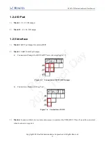
Page 16: ...MIC Test Jumper for external MIC 2 Mark 3 UART LOG Test Jumper a Connection of Jumper for HCI UART Test is shown in figure 1 5 Figure 1 5 Connection of HCI UART Jumper b Connection of Jumper for Log Test Figure 1 6 Connection of LOG 3 Mark 6 G sensor which is a 6 axis motion sensor is powered by VDD_DEV Thus J6 need be connected when G sensor is required R e a l t e k f o r 2 0 2 1 T e c h D a y ...

Page 17: ...t configured If SPI interface is applied R1 need be removed Connect test point AD0 and nCS to specified IO port with SDO and nCS jump wire respectively and then short J18 and J19 with jumper Figure 1 7 G sensor I2C connection 5 Mark 12 Micro USB interface It can be used as UART communication port when connected to PC 6 Mark 20 SWD interface used for SWD debug 1 2 6 Others 1 Mark 16 4 independent L...

Page 18: ...Os that not listed in table 1 1 to control LEDs LEDs can be connected to specified IO port with jump wire 3 Mark 18 RESET key and 5 independent keys as shown in Figure 1 9 Note Debouncing capacitors and internal pull up resistor make up a filter circuit to reduce ripples when buttons are pressed However it can also affect the result of keyboard array scan Capacitors are not mounted on board by def...

Page 19: ...KF socket DJF P0_0 P0_0 P0_0 P0_0 P0_0 P0_0 M0_0 P0_1 P0_1 P0_1 P0_1 P0_1 P0_1 LED0 M0_1 P0_2 P0_2 P0_2 P0_2 P0_2 P0_2 LED1 M0_2 P0_3 P0_3 P0_3 P0_3 P0_3 P0_3 LOG M0_3 P0_4 P0_4 P0_4 P0_4 P0_4 P0_4 M0_4 P0_5 P0_5 P0_5 P0_5 P0_5 P0_5 M0_5 P0_6 P0_6 P0_6 P0_6 P0_6 P0_6 M0_6 P0_7 P0_7 P0_7 P0_7 P0_7 P0_7 M0_7 P1_0 P1_0 P1_0 P1_0 P1_0 P1_0 SWDIO M1_0 P1_1 P1_1 P1_1 P1_1 P1_1 P1_1 SWDCLK M1_1 P1_2 P1_2...

Page 20: ..._7 P2_7 P2_7 MIC_P M2_7 P3_0 P3_0 P3_0 P3_0 P3_0 P3_0 UART_T X M3_0 P3_1 P3_1 P3_1 P3_1 P3_1 P3_1 UART_R X M3_1 P3_2 P3_2 P3_2 P3_2 P3_2 P3_2 ICM2061 M3_2 8_I2C_S CL P3_3 P3_3 P3_3 P3_3 P3_3 P3_3 ICM2061 8_I2C_S DA M3_3 P3_4 P3_4 P3_4 P3_4 P3_4 P3_4 M3_4 P3_5 P3_5 P3_5 P3_5 P3_5 P3_5 KEY4 M3_5 P3_6 P3_6 P3_6 P3_6 P3_6 P3_6 M3_6 P4_0 P4_0 P4_0 P4_0 P4_0 P4_0 SPI0_CL K KEY0 SWO M4_0 P4_1 P4_1 P4_1 P...

Page 21: ...t is shown in Figure 2 1 Figure 2 1 LOG out connection 2 2 Current test The following current test points are reserved on evaluation board VDD_DEV is peripheral power supply of EVB VDD_BAT powers VBAT and HVD on EVB VDD_IO powers VDD_IO on RTL8762D chips some of packages have no independent VDD_IO Pin Figure 2 2 Schematic of Power jumpers on EVB J23 shall be disconnected when testing power consump...

Page 22: ...3 6 axis Motion Sensor 6 axis motion sensor is powered by VDD_DEV so J6 needs to be connected before using G sensor If I2C interface is applied J18 and J19 should be shorted with jumper That is to say connect I2C signal line to M3_2 and M3 3 INT single line can be connected to M2_2 via J20 and can be left not connected if INT function is not configured If SPI interface is applied R1 need be remove...

Reviews: