

User’s Manual
GSM35
6
RTD Finland Oy
Chapter 5 Board operation and programming..... 23
Defining the memory map .................................................................... 23
GSM BASE+400h Digital I/O................................................................. 24
GSM BASE+402h status register .......................................................... 24
GSM BASE+403h control register......................................................... 24
Starting up and logging into the GSM network...................................... 25
Interrupts ............................................................................................... 25
Chapter 6 GSM35 Specifications .......................... 31
Chapter 7 Return policy and warranty.................. 32
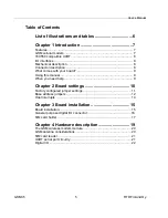
List of illustrations and tables
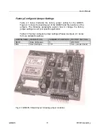
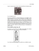
Fig. 2-1 GSM35 Board layout showing jumper locations
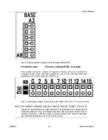
Fig. 2-2 Base address jumpers illustrating address 2E8h
Fig. 2-3 Interrupt jumpers from left to right: IRQ 2,5,6,7,10,11,12,15 and G
Fig. 3-1 GSM35 integrated in a RTD PC/104 cpuModule stack
together with a HPWR104HR and a CMM series cpuModule
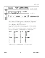
Fig. 3-2 Digital I/O connector layout of the GSM35
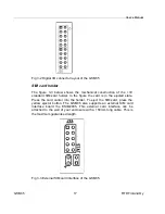
Fig. 3-3 External SIM card interface of the GSM35
Fig. 3-4 ESIM2035 External SIM card interface board
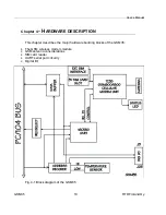
Fig. 3-5 External SIM card header J25 (Only on GSM35-2 boards)
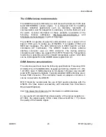
Fig. 4-1 Block diagram of the GSM35
Table 2-1 Factory configured jumper settings
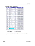
Table 2-2 Base address jumper settings GSM35
Table 3-1 Pin outs of the GSM35 digital I/O interface connector
Table 5-1 General I/O map of the GSM35 UART


