


16
2.3
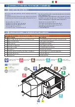
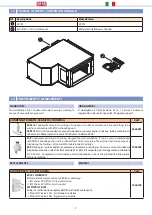
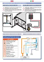
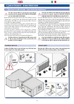
HYDRAULIC CONNECTIONS
| COLLEGAMENTI IDRAULICI
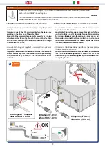
COLLEGAMENTO VALVOLA H
2
O OBBLIGATORIA
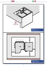
ATTENZIONE: è obbligatorio installare la valvola nel
caso di abbinamento DA+SR.
ATTENZIONE: la valvola va installata solo nella linea
di pre-trattamento e non deve intercettare in nessun
modo la linea di post-trattamento.
NECESSARY H
2
O VALVE CONNECTION
WARNING: The use of the valve is compulsory in case
of combination between DA and SR units.
WARNING: The optional valve must be installed in the
pre-treatment line only and should not interfere with
the post-treatment line.
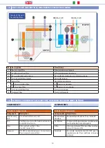
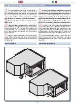
WIRING DIAGRAM FOR COMPLETE HYDRAULIC CONNECTION
SCHEMA DI COLLEGAMENTO IDRAULICO COMPLETO
GND
- BLACK
/ NERO
Y
- GREY
/ GRIGIO
+24 V
- RED
/ ROSSO
6
9 10
0
0 7 8
AB
A
B
Kv
4,03
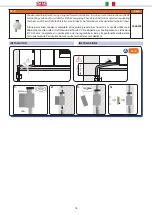
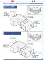
SCHEMA IDRAULICO CON VALVOLA MODULANTE
HYDRAULIC DIAGRAM WITH MODULATING VALVE
IN (B)
OUT (A)
IN (D)
(E)
OUT (C)
Tank
Accumulo
Drain
Scarico
DA
701
PRE
CO
ND
AB
A
B
KEY
/ LEGENDA
Circulation pump
Circolatore
Flow rate lockshield
Detentore di regolazione portata
Condensation drain kit
Kit scarico condensa
On/Off Valve
Valvole di intercettazione
Non-return valve
Valvola di non ritorno
Flowmeter
Misuratore di portata
Recommended components
Componenti consigliati
Modulating valve for DA unit
Valvola modulante per DA
Kv 4,03
Summary of Contents for SR 701
Page 2: ......
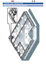
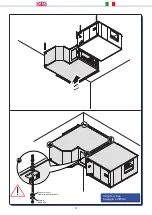
Page 11: ...11 2 INSTALLATION INSTALLAZIONE 2 1 DISTRIBUTION EXAMPLE ESEMPIO DI DISTRIBUZIONE ...
Page 35: ......