


UPM-421
6-CHANNEL CONTROL PANEL
5
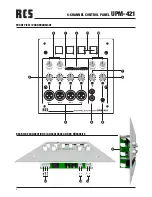
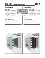
BEDIENELEMENTE UND ANSCHLÜSSE
1. Betriebsbereitschaftanzeige
2. LED Aussteuerungsanzeige des Summensignals
3. Höhen- und Tiefenregler für die Mikrophon-Signale
1 bis 4
4. Eingangs-Level-Regler für die Mikrophon-Eingänge
1 bis 4 mit Signal-Anzeige LED
5. XLR Mikrophon-Eingänge 1 bis 4
6. Cinch LINE-Eingang
7. Eingangs-Level-Regler für LINE
8. iPod
®
(AUX)-Eingang auf 3,5 mm Klinke
9. Eingangs-Level-Regler für iPod
®
/AUX
10. Höhen- und Tiefenregler für das LINE und iPod
®
/
AUX Signal
11. Leerfeld für bis zu 4 optional erhältliche Funktions-
schalter (DSB-400)
12. Elektronisch symmetrischer Audio Ausgang zum
Endverstärker
13. Lampen Ausgang für Beleuchtung der optionalen
Funktionsschalter (DSB-400)
14. Anschluss der Betriebsspannung 24V=
15. Schalter zum ändern des Ausgangspegel von 0dB
auf +6dB
OPERATING ELEMENTS AND CONNECTIONS
1. Operation display
2. LED modulation display of the buzzing signal
3. High and Low regulator for microphone signals
1 – 4
4. Input-level-control for microphone input 1 – 4 with
signal-LED
5. XLR microphone inputs 1 – 4
6. Cinch Line-input
7. Input-level-control for LINE
8. iPod
®
(AUX) input on catch (3.5 mm jack)
9. Input-level-control for iPod
®
/AUX
10. High and low control for LINE and iPod
®
/AUX si-
gnal
11. Space for up to 4 optional available functional swit-
ches (DSB-400)
12. Electronic balanced audio output to connect an
Amplifier
13. Lamp output, for the lights of the optional function
switches (DSB-400)
14. Connection for power supply 24V=
15. Switch to change the output-gauge from 0dB to
+6dB