


- 2 -
INSTALLING THE
#
OMEGA-3v9s
ESC
.
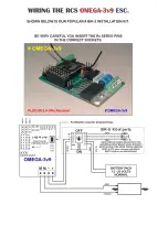
We usually supply the
#
OMEGA-3v9s
ESC
with a Lemon brand Rx which is simply plugged in upside down on the ESC
pcb in the 24 pin socket. The two parts are bench tested to make sure they work correctly.
It is most important the two parts line up correctly. Pin positions are marked on both the back Rx and ESC.
Servo leads are not needed.
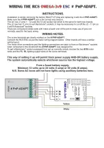
You can obtain the ESC without an Rx supplied and you can use one of your choice. As long as the servo pin outs on the
Rx & ESC match. If they do not match, RCS has a prewired adaptor # Rx-ADAPT with four servo cables.
THESE INSTRUCTIONS REFER SPECIFICALLY FOR USE WITH THE
RCS
TX-4, TX-8 & TX-20 HANDPIECES.
IT CANNOT BE USED WITH ODD NUMBERED TX HANDPIECES. CONTACT RCS TO USE A STICK RADIO.
YOU CAN ONLY MIX BRANDS OF R/C IF THEY ARE DSM2.
THE
RCS
#
OMEGA-3v9s
SYSTEM IS ONE PART INTO WHICH YOU PLUG ALMOST ANY DSM2 or DSMX RX.
OR
; USE ANY BRAND OF R/C WITH THE OPTIONAL EXTRA # Rx-ADAPT ON THE ESC AND PLUGGED INTO THE
APPROPRIATE CONNECTIONS ON THE RX. PLEASE NOTE. PDF WIRING INSTRUCTIONS ARE HERE:
http://www.rcs-rc.com/pages/instructions
THESE INSTRUCTIONS REFER TO OUR OWN DSM2 TX-8 TX HANDPIECES.
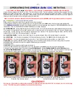
CONTROL FUNCTIONS.
The
TX-4,
TX-8 & TX-20
handpieces use a spring loaded SPDT switch for selecting direction change & a large knob for
speed control. Apart from direction change, the operation is exactly the same as for the odd numbered TX handpieces.
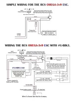
USING EXTRA SERVOS.
The
#
OMEGA-3v9s
ESC
permits the operation of a regular servo using Ch # 5. Simply plug the servo leads the right
way around into the Ch # 5 servo header so marked in the RX. See the ESC diagram.
Servo outputs for channels 6 & 7 are available for use only with a 7 channel Tx.
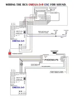
SOUND TRIGGER CONTROLS. TX-8.
The
TX-8
has four pushbuttons on the handpiece that are intended to trigger 4 x sound effects or control accessories.
They operate F1, F2, F3 & F4 on this ESC. The Ch 5 pushbutton is available for a servo control feature such as Kadee
servo uncoupling.
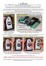
A pushbutton on the
ESC
pcb is used for initial speed calibration and making system program changes such as Start/Max
voltage, default direction start, system reset & sound trigger outputs from momentary to latch ON
– OFF. If you need to
calibrate the system proceed to page # 6. Or: See URL on page # 1.
LOCOMOTIVE SEPARATION.
2.4 GHz R/C systems are not separated with crystals. Every TX has a unique identifier code. They are all legal for air &
ground use.
Most SPEKTRUM RX’s (and DSM2/DSMX clones) can be
“BOUND”
to the TX-xx handpieces.
“BINDING”
must be done before the system can be used. See page # 4.
You can mount the
#
OMEGA-3v9s
PCB with double stick tape or non conductive silicone. Do not allow metal objects to
touch the rear of the PCB. Damage to the PCB may result.
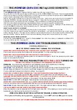
Plug in the Rx.
It is most important that pin #’s line up..
Push Rx firmly into place for best
connectivity.
Rx in position.
Bend aerials up slightly.
PLACING RX ANTENNA.
It does not matter where you place the RX and antenna(s). We have at least 15
0’ + range with the system in plastic
locos. There is
NO
“glitching” or “Rusty Bolt Effect”. 2.4 GHz RX’s have been successfully used for some years with the
RX & antenna inside a dummy water tank of a live steam loco and inside expensive brass electric locos.
Turn the 2.4 GHz TX OFF to save the batteries & the loco will “Cruise” along until the TX is turned ON again & manual
control resumed.
N.B. Not the low cost manua
l bind RX’s.
They have pre-set Failsafe settings.