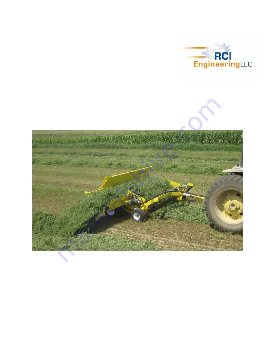
RCI 186M Operator'S Manual Download Page 1


186M Windrow Merger 


Operator Manual 


Includes operating, adjustment, maintenance, technical, 

repair parts and safety instructions for the 186M Windrow Merger. 


Please retain this document for future reference.  Keep this manual available for reference to the 
operator at all times. Do not allow anyone to operate this implement without reading and fully 
understanding this operator manual.  Never allow children to operate on or near any equipment at 
any time. 


RCI Engineering LLC 


RC130102  Rev B   1Nov2017 

www.RCIengineering.com 

Copyright © 2017 by RCI Engineering LLC 

Summary of Contents for 186M

Page 1: ...cument for future reference Keep this manual available for reference to the operator at all times Do not allow anyone to operate this implement without reading and fully understanding this operator manual Never allow children to operate on or near any equipment at any time RCI Engineering LLC RC130102 Rev B 1Nov2017 www RCIengineering com Copyright 2017 by RCI Engineering LLC ...

Page 2: ... standard shipping costs for the replacement parts 3 Used equipment 4 Components covered by their own non RCI warranties such as tires and trade accessories 5 Normal maintenance service and expendable high wear items 6 Sacrificial components designed to fail to prevent damage to other components when obstructions are encountered i e shear bolts pickup teeth 7 Repairs or adjustments caused by impro...

Page 3: ...se the extension length to 5 is available and recommended when tripling 16 or 18 cut widths to a windrow of less than 8 wide If tripling windrows from a 16 cut width and a final windrow width of under 9 is needed the standard extension is sufficient The longer extension option is recommended for all cut widths of greater than 16 Windguard is standard equipment Pickup and belts are driven hydraulic...

Page 4: ...length Setup Time Approximately 2 hours of setup time is required from shipping configuration to field operation when shipped on a skid When shipped via flatbed trailer the unit requires approximately 30 minutes of setup time for preparation to the field RCI Engineering LLC also offers an assortment of attachments for John Deere hay and forage equipment to improve performance increase efficiency a...

Page 5: ...6 68 Delivery Checklist 8 70 Safe Operation of Machine 10 Safety Warning Signs 11 Safety Sign Locations 12 Safety Sign Definitions 13 Setup Instructions 15 Field Operation 17 Adjustments 20 Maintenance 25 Service 26 Troubleshooting 32 Hydraulic Functional Schematic 34 Bolt and Screw Torque Values 36 Repair Parts 38 Parts Index 40 ...

Page 6: ...th in 32 1 2 Extension Yes Length 36 Standard 60 Optional Extension Folding Hydraulic Belt Drive Hydraulic Tractor Hyd Drive System Yes GPM PSI Required 12 2000 Hydraulic Remotes Needed 2 Tractor Size Minimum 50 hp Dimensions other Specifications Base Weight lbs 2 200 approx Transport Width 10 11 Transport Length 12 Tire Size Frame 26 x 12 12 Gauge Wheel Size 18 5 x 8 5 8 Operating Speed 2 to 12 m...

Page 7: ...ly Gauge wheels installed and inflated properly All moving parts operate freely Belt tension set properly Extension belt tension set properly All applicable warranty information recorded I acknowledge that the pre delivery service was performed and the unit is ready for delivery to the customer ________________________ _________________________ ___________________ Dealership s Name Representative ...

Page 8: ...7 This Page Intentionally Left Blank ...

Page 9: ... and long life Show how to properly adjust the belt tension as instructed in the Adjustments section Make it be known that if the customer can visit or call the dealership to discuss any questions or problems they may encounter Complete the Owner s Registration with the customer ensure it is completely filled out and return it to RCI Engineering _________________________________ Date Delivered ___...

Page 10: ...9 This Page Intentionally Left Blank ...

Page 11: ...should become illegible or be missing 3 Avoid loose fitting clothing while operating this implement The operator should always wear close fitting clothing and sturdy footwear 4 Before operation of this implement become familiar with all controls of the prime mover and implement and understand the function of this implement 5 Check all guards and shields to make sure they are in place and functiona...

Page 12: ...information regarding the hazard The top or left box of the decal indicates a warning for the hazard The triangle indicates WARNING The symbol inside the triangle indicates what the warning pertains to In some cases a simple explanation mark is used The right or bottom box of the decal indicates an instruction on how to respond to the hazard Reference each decal to the operator manual for further ...

Page 13: ...12 Safety Sign Locations Decal locations are identified in the figures below and referenced on the following pages ...

Page 14: ...for transport Ensure that these decals are clearly visible and clear of debris before transporting unit Safety Sign 4 This safety sign is a warning of injury due to escaping hydraulic fluid under pressure Keep away from this area when the hoses have hydraulic pressure to avoid the hazard Failure to do so may result in serious injury Safety Sign 5 This safety sign is a warning of entanglement of mo...

Page 15: ...ure is critical to proper machine operation and reliability This decal is located on the tongue of the unit near the jack stand storage position Safety Sign 9 This safety sign is a Slow Moving Vehicle Sign and is provided to meet the requirements of on road transportation Always make sure this decal is complete clean and visible to the rear of the implement whenever transporting the machine on pub...

Page 16: ...15 This Page Intentionally Left Blank ...

Page 17: ... tongue and replace the bolts provided Torque bolts to 280 lb ft 380 Nm See Figure 9 5 Install Jack Stand and Hydraulic Hoses as indicated in Figure 9 Slots are provided for hose storage when not in use 6 Lift the unit with a forklift from the rear through the fork pockets in the main frame Take care to not damage any tine bars or tines Secure the merger to the forklift in a safe manner Do not mov...

Page 18: ... pin at hydraulic cylinder Install spring at pivot link See Figure 10 10 Grease unit See Maintenance Section of this manual 11 Verify tire pressures are set correctly See Service section of this manual 12 Use the shipping blocks to create a ramp in front of the skid at the tires Connect the unit to a tractor and pull from the shipping skid See Attach Merger to Tractor in the next section Figure 10...

Page 19: ...may contain hydraulic pressure Do not disconnect or service hydraulic systems with pressure in the system Relieve all pressure before performing any service work Beware of components that may move when changing selections with valves or removing locking mechanisms Failure to do so may result in serious injury 2 Disengage tractor put the tractor in park shut off the engine and remove the key from t...

Page 20: ...n was used slowly switch hydraulic valve near jack storage position to the OPEN position See Engage Disengage Extension Folding in the next section If the extension was not used proceed to next step but skip Steps 5 and 6 3 Raise the pickup to the highest position to allow the transport lock to fall into place Continue to raise the pickup to raise the extension to transport position Verify the tra...

Page 21: ...ecrease spring tension and result in higher ground pressure Gauge Wheel Adjustment To adjust the gauge wheels the unit must be raised to transport position and the transport lock must be engaged See Engage Disengage Transport Lock in this section With the tractor disengaged in park and engine off with the key removed remove adjustment bolt Key 1 Figure 12 Move gauge wheel support bracket Key 2 Fig...

Page 22: ...rcuit as the pickup raise lower circuit The extension raise lower function is enabled or disabled by use of a hand controlled hydraulic valve located on the tongue near the jack stand storage location To raise the extension first ensure there is no hydraulic pressure in the system WARNING Hydraulic systems at rest may contain hydraulic pressure Do not disconnect or service hydraulic systems with p...

Page 23: ...s to turn the hand valve as component damage may result To disengage the extension motor push the manual valve on the manifold in slightly turn counterclockwise and pull the valve out Windguard Adjustment The windguard is adjustable for stop positions in a raised and lowered position The default position is such that the windguard tines are positioned directly above the pickup tines such that no p...

Page 24: ...use the tractor hydraulic system to overheat The manifold on the merger protects the motors from over speed but not from overheating IMPORTANT Depending on tractor make and model engine speed can impact the hydraulic oil flow to the merger during this process Always set the tractor engine rpm to desired operating speed before setting merger hydraulic speeds Note A new manifold is used starting wit...

Page 25: ...er hydraulics reinstall the plugs under the cartridges Pickup Speed Adjustment Open Center Systems The tine speed is adjustable in series with the belt speed by adjusting hydraulic oil flow WARNING Only adjust the belt speed when the tractor is turned off park brake is set key is removed and all pressure is relieved from the system and unit is lowered to the ground IMPORTANT For open center tracto...

Page 26: ...immediately Grease fitting locations 1 Gauge wheels adjusters at 1 place on each end See Figure 20 2 Pickup raise lower pivot pins at 1 place on each end See Figure 21 3 Wheel clutches at outer housings within wheel well on each side See Figure 22 Inspect pickup cylinder tines and tine bar guards daily for damage Replace damaged tines immediately to prevent further damage to other tines and the ti...

Page 27: ...he cam bearing bolt 5 Replace the cam bearing 6 Reassemble components using red loctite on the cam bearing bolt SPECIFICATION Cam bearing bolt torque 46 lb ft 63 N m MUST USE RED LOCTITE Straightening Bent Tines There should be approximately 6 150 mm gap between the point of tine disappearance and the end of the slot If the distance is different bend the tine back to the original position of 6 150...

Page 28: ...lip with cup side towards bolt head round edge towards tine Failure to do so may result in premature failure of tine See Figure 25 5 Replace the tine guard Tine Bar Guard Replacement Damaged tine bar guards must be replaced immediately to prevent damage to other components To replace a damaged tine bar guard remove all four retaining bolts The guard will now slide forward for removal See Figure 26...

Page 29: ...e 27 Verify the main belt is clean and in proper alignment on grooves and the frame before and after tensioning Extension Belt Tension The extension belt is adjusted manually and must be adjusted regularly so the belt does not sag more than 3 4 19 mm at the bottom between the rollers To adjust the extension belt first loosen the four carriage bolts Key 1 Figure 28 that hold each adjuster plate in ...

Page 30: ...inforced rubber Although designed for durability the following is important to consider to maximize the life of the belt 1 Always store the unit out of direct sunlight in a cool dry place free of rodents 2 Always keep the belt and rollers free of debris moisture when not in use oil grease and any other chemicals that may affect the belt 3 Do not treat the belt with any belt dressing of any kind 4 ...

Page 31: ...grease and any other material that will draw moisture and cause rust 2 Thoroughly lubricate the merger as described in the Maintenance section 3 Paint all parts where the paint has been removed 4 Store merger with transport lock in place and extension in the transport position 5 Store in a dry place out of the elements if possible 6 Order and replace any parts needed for next season ...

Page 32: ...31 This Page Intentionally Left Blank ...

Page 33: ...into the ground Gauge wheels are too high Adjust gauge wheels Float improperly adjusted Adjust float Tines do not revolve Obstruction to pickup Clear obstruction Broken cam Replace cam Tines bend break Ground clearance too low Adjust float or gauge wheels Foreign material inside tine guides Remove material Crop is blown out of pickup tines by the wind Windguard is in raised position Adjust windgua...

Page 34: ...33 This Page Intentionally Left Blank ...

Page 35: ...34 Hydraulic Functional Schematic ...

Page 36: ...35 This Page Intentionally Left Blank ...

Page 37: ...36 Bolt and Screw Torque Values ...

Page 38: ...37 This Page Intentionally Left Blank ...

Page 39: ...e frame rail Replacement Hardware All bolts cap screws washers and machine screws are standard grade 5 and zinc plated unless markings on the part indicate otherwise The use of improper hardware in any location can result in the failure of the component fastened with the hardware or related structures and can cause personal injury further damage to the product or loss of property Replacement Parts...

Page 40: ...39 This Page Intentionally Left Blank ...

Page 41: ...s 41 Hitch Pivot Components 43 Pickup Components 45 Conveyor Components 49 Extension Components 51 Long Extension Components 53 Windguard Components 55 Motor and Manifold Components 57 Hydraulic Components 59 Decals Left 61 Decals Right 63 Decals Back 65 ...

Page 42: ...41 Hitch And Wheel Components ...

Page 43: ...ylock 1 24 RC900703 Washer 3 4 SAE YZ Flat 4 25 RC900686 Washer 1 2 SAE YZ Flat 4 26 RC901869 Pin 1 4 X 1 1 2 Spring 2 27 RC900615 Nut 5 8 11 YZ Hex Jam 2 28 RC901872 Screw 1 4 20 x 5 8 Thread Cutting 3 29 RC901874 Screw 1 4 20 x 2 Thread Cutting 2 30 RC900102 Bolt 3 8 16 x 2 5 Gr 5 YZ Hex 2 31 RC900696 Washer 5 8 SAE YZ Flat 18 32 RC901647 Bolt 1 2 13 x 1 3 4 CZ Carriage 1 33 RC900063 Bolt 5 16 1...

Page 44: ...43 Hitch Pivot Components ...

Page 45: ...YZ Flat 1 12 RC900686 Washer 1 2 SAE YZ Flat 2 13 RC901866 Washer 1 2 Belleville 1 14 RC900677 Washer 3 8 SAE YZ Hard Flat 4 15 RC900093 Bolt 3 8 16 x 1 1 2 Gr 5 YZ Hex 2 16 RC900831 Pin 3 16 X 1 CZ Cotter 1 17 RC901873 Zerk 1 8 NPT Straight Grease 1 18 RC900102 Bolt 3 8 16 x 2 5 Gr 5 YZ Hex 1 19 RC900696 Washer 5 8 SAE YZ Flat 3 20 RC900583 Nut 3 8 16 YZ Nylock 2 21 RC900524 Nut 3 8 16 YZ Hex 2 2...

Page 46: ...45 Pickup Components ...

Page 47: ...20 x 1 75 Gr 5 CZ Hex 12 Red Loctite RC024397 22 RC063292 Cam Inner 4 23 RC063293 Cam Outer 4 24 RC063182 Guard RH End Tine Bar 1 25 RC063257 Cover 2 26 RC063453 Guard 33 27 RC063186 Assembly Bearing 1 28 RC082419 Hub Motor 1 29 RC082015 Motor Hydraulic 1 30 RC082422 Assembly Tube 1 31 RC900588 Nut 1 2 13 YZ Nylock 19 32 RC901645 Screw 1 2 13 x 1 3 4 Countersunk Allen 2 33 RC901646 Screw 3 8 24 x ...

Page 48: ...47 This Page Intentionally Left Blank ...

Page 49: ... FORB Reducer 2 48 RC901878 Bolt 1 2 20 x 1 1 4 Gr 8 YZ Hex 10 49 RC901638 Pin 1 8 x 2 SS Cotter 2 50 RC901890 Nut 1 20 Castle 1 51 RC900071 Bolt 5 16 18 x 2 1 2 Gr5 YZ Hex 12 52 RC902153 Screw 3 8 24 X 3 8 BO Button Socket Cap 4 53 RC902152 Key SQ 5 16 x 1 1 54 RC700309 Adapter 8 MORB 8 MFS 90 Elbow 2 ...

Page 50: ...49 Conveyor Components ...

Page 51: ...ler 1 13 RC063363 Roller Idler 1 14 RC130055 Deflector 1 15 RC901558 Bolt 5 16 18 x 1 CZ Carriage 29 16 RC900686 Washer 1 2 SAE YZ Flat 2 18 RC901628 Washer M12 Fender 4 19 RC900659 Nut 1 4 20 YZ Serated Flange 2 20 RC900677 Washer 3 8 SAE 12 21 RC900672 Washer 5 16 SAE YZ Flat 29 22 RC900579 Nut 5 16 18 YZ Nylock 29 23 RC900404 Bolt 3 8 16 x 1 1 4 CZ Carriage 12 24 RC900583 Nut Nylock 3 8 16 12 2...

Page 52: ...51 Extension Components ...

Page 53: ...3363 Roller Idler 1 17 RC063371 Fitting Orifice 2 18 RC900588 Nut 1 2 13 YZ Nylock 4 19 RC900282 Bolt 1 2 13 x 1 1 2 Gr 8 YZ Hex 1 20 RC900731 Washer Lock 1 2 1 21 RC901867 Bolt 1 2 13 x 4 Gr5 CZ Tap 2 22 RC901558 Bolt 5 16 18 x 1 CZ Carriage 11 23 RC900686 Washer 1 2 SAE YZ Flat 5 24 RC900677 Washer 3 8 SAE 10 25 RC900672 Washer 5 16 SAE YZ Flat 11 26 RC900726 Washer Lock 5 16 8 27 RC900579 Nut 5...

Page 54: ...53 Long Extension Components Optional ...

Page 55: ...cription Qty Comments 1 RC063462 Extension 1 2 RC063479 Belt Extension 1 3 RC063461 Seal 2 4 RC901558 Bolt 5 16 18 X 1 CZ Carriage 16 5 RC900672 Washer 5 16 SAE YZ Flat 16 6 RC900579 Nut 5 16 18 YZ Nylock 16 7 RC130109 Belt Pin 1 8 RC063499 Manual Operator 1 ...

Page 56: ...55 Windguard Components ...

Page 57: ...her 2 5 RC063290 Bracket LH Pivot 1 6 RC063282 Bushing Pivot 4 7 RC063285 Retainer 2 8 RC900588 Nut 1 2 13 YZ Nylock 4 9 RC900686 Washer 1 2 SAE YZ Flat 8 10 RC900677 Washer 3 8 SAE YZ Hard Flat 4 11 RC900093 Bolt 3 8 16 x 1 1 2 Gr 5 YZ Hex 2 12 RC900834 Pin 3 16 x 2 Cotter 2 13 RC900137 Bolt 1 2 13 x 2 Gr 5 YZ Hex 4 14 RC900583 Nut 3 8 16 YZ Nylock 2 ...

Page 58: ...57 Motor and Manifold Components ...

Page 59: ...677 Washer 3 8 SAE 8 9 RC900685 Washer 7 16 SAE YZ Flat 4 10 RC900729 Washer 7 16 YZ Lock 4 11 RC901863 Bolt 7 16 14 x 1 Gr 5 YZ Hex 4 12 RC900728 Washer 3 8 YZ Lock 8 13 RC900088 Bolt 3 8 16 x 1 Gr 5 YZ Hex 8 14 RC900575 Nut 1 4 20 YZ Nylock 2 15 RC700084 Adapter 8 MFS 10 MORB Straight 10 16 RC700126 Adapter 8 MFS 10 MORB 90 Elbow 2 1 For implement s n RCIX00834 and higher Replaces previous versi...

Page 60: ...59 ...

Page 61: ...DAPTER TEE 6 MFS 6 MORB 1 F6 RC700084 ADAPTER Straight 8 MFS 10 MORB 10 F9 RC700118 ADAPTER 90 deg Elbow 6 MFS 6 MORB 1 F10 RC700634 ADAPTER 10 MORB REDUCER 8 FORB 2 F11 RC700309 ADAPTER ELBOW 90 DEG 8 MORB 8 MFS 2 1 For other hydraulic components see previous page 2 This layout effective for implement s n RCIX00834 and higher For units up to s n RCX00833 components are the same except for the man...

Page 62: ...61 Decals Left ...

Page 63: ...ng Left 2 2 RC901936 Decal Tire Pressure 1 3 RC901934 Decal Read OPM 1 4 RC901939 Reflector Yellow 2 x 9 2 5 RC901933 Decal Grease 2 6 RC902035 Decal ISO Pinch Point Hazard Horizontal 1 7 RC901932 Decal ISO Entanglement Hazard 1 8 RC901935 Decal ISO High Pressure Fluid Hazard 1 ...

Page 64: ...63 Decals Right ...

Page 65: ...omments 1 RC130101 Decal 186M Long Right 1 2 RC901939 Reflector Yellow 2 x 9 2 3 RC902035 Decal ISO Pinch Point Hazard Horizontal 1 4 RC901933 Decal Grease 3 5 RC901932 Decal ISO Entanglement Hazard 1 6 RC901935 Decal ISO High Pressure Fluid Hazard 1 ...

Page 66: ...65 Decals Back ...

Page 67: ... Reflector Orange 2 X 9 2 3 RC130099 Decal 186M Rectangle 1 4 RC901932 Decal ISO Entanglement Hazard 3 5 RC901937 Decal American Flag 1 6 RC902035 Decal ISO Pinch Point Hazard Horizontal 2 7 RC901938 Decal SMV 1 8 RC901934 Decal Read OPM 1 9 RC901933 Decal Grease 1 10 RC901924 Tag RCI Serial Number 1 ...

Page 68: ...67 This Page Intentionally Left Blank ...

Page 69: ...nstalled properly Gauge wheels installed and inflated properly All moving parts operate freely Belt tension set properly Extension belt tension set properly All applicable warranty information recorded I acknowledge that the pre delivery service was performed and the unit is ready for delivery to the customer ________________________ _________________________ ___________________ Dealership s Name ...

Page 70: ...69 This Page Intentionally Left Blank ...

Page 71: ...n and long life Show how to properly adjust the belt tension as instructed in the Adjustments section Make it be known that if the customer can visit or call the dealership to discuss any questions or problems they may encounter Complete the Owner s Registration with the customer ensure it is completely filled out and return it to RCI Engineering _________________________________ Date Delivered __...

Page 72: ...71 208 River Knoll Drive Mayville WI 53050 920 387 9804 Fax 920 387 9806 www rciengineering com ...

Reviews: