DESIGNATION
TRANSMITTER GAIN
@
PEAK MODULATION
INDICATOR
CARRIER OUT-IN
®
CHANNEL 1-2-3-4
©
RECEIVER GAIN
®
SPEECH CLARIFIER
®
SPEAKER-HANDSET
®
LOCAL-REMOTE
©
REMOTE INDICATORS
-1-2-3
TELEGRAPH-PHONE
®
POWER
®
POWER
RECEIVER
®
RECEIVER
TRANSMITTER
©
TRANSMITTER
PHONES
KEY
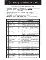
TABLE 1 - FUNCTIONS OF CONTROLS AND INDICATORS
TYPE OF CONTROL
FUNCTION
TRANSMITTER-RECEIVER UNIT
Potentiometer
Neon lamp
(red)
Rotary switch
(2 positions)
Rotary switch
(4 positions)
Potentiometer
Trimmer capacitor
Adjusts gain of transmitter. Normally set while
talking for occasional flashing of PEAK MOD
ULATION INDICATOR.
Indicates degree of modulation.
Permits communication with conventional AM
systems.
At OUT position, SSB-1 operates as a single
sideband, suppressed carrier equipment.
At IN position, carrier is not suppressed and
SSB-1 operates as an AM system with a single
sideband.
Selects predetermined operating frequency of
transmitter and receiver. Frequencies are as
marked.
Adjusts gain of receiver. Normally set for low
level background noise when monitoring a channel,
or for desired volume when receiving.
Compensates for slight frequency differences be
tween two SSB-1's. Nqrmally set for clear voice
reproduction.
POWER SUPPLY UNIT
Toggle switch
(2 positions)
Rotary switch
(4 positions)
Neon lamps
(white)
Toggle switch
(2 positions)
Toggle switch
(2 positions)
Neon lamp
(white)
Toggle switch
(2 positions)
Neon lamp
(Amber)
Toggle switch
(2 positions)
Neon lamp
(retl)
Telephone jack
Telephone jack
24
Selects either handset or speaker for receiver
output.
Selects operation from either local handset or
up to three remote (extension) desk sets.
Remote lamp lights when respective extension is
in use.
At TELEGRAPH, CW telegraph or tone SSB
transmission may be used. At PHONE, telephone
signals only are used.
In on position, line power is brought into power
supply. 6.3V ac is applied to crystal ovens and
to keying relay through key.
Indicates application of line power to power
supply.
Applies operating voltages to receiver.
Indicates receiver power supply is energized.
Applies operating voltages to transmitter.
Indicates transmitter power supply is energized.
Provides local monitoring facilities for remote
operation. (Listen only)
Provides connection for external telegraph key.
Summary of Contents for SSB-1
Page 1: ...t z LA I E a I I Cl LA I I z z C cc t LA I cc c en U z I LA I 0 IE en CD IE z Cl C U c ...
Page 4: ... ...
Page 32: ... a c CD c a 00 CD n 0 1 CD 1 CD a ...
Page 42: ...z 0 1 3 t r l r n ...
Page 44: ...R i5 Rl23 Cl22 T R114 c Figure 17 Power Supply Bottom View 40 116 rs as6 I J I I I I ...
Page 45: ... f f c t f c f f f t f f c c c t c f c f f f Figure 18 Speech Clipper Internal View 41 ...
Page 46: ...5 5 01 FRONT SOTTOM COVER OPEN 18 1 8 Figure 19 Remote Desk Set 42 I I I I I I J ...
Page 77: ......
Page 78: ......
Page 79: ......


