background image

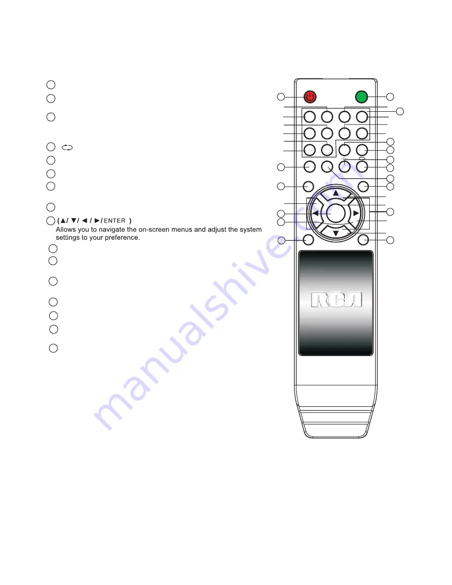
Remote Controller

9

POWER

MUTE

1

5

9

2

6

0

3

7

4

8

P.MODE

S.MODE

SLEEP

MENU

DISPLAY

EXIT

SOURCE

MTS

ENTER

7

15

14

13

12

10

10

11

3

4

5

6

8

9

1

2

16

3

0--9

Press 0~9 to select a TV channel directly while watching

TV. The channel will change after 2 seconds.Applicable for
entering page number in teletext mode and so on.

2

Press to mute the sound. Press again or press

MUTE :

VOL+ to unmute.

1

Sets your TV to power on or standby mode.

POWER :

4

:

Return to the previously viewed program.

5

Press to scan through or to select a channel.

CH +/- :

6

Press to increase / decrease the sound level.

V +/-:

7

- /- -

Press this button to enter a program number for

different digit. eg. -/ - - / ---

8

Press to display the source and channel's info.

DISPLAY :

9

10

SOURCE:

Press to list the source items.

11

SLEEP:

Select amount of time before TV turn itself

off automatically.

12 E

Exits from the menu or sub-menu and menus and adjust

XIT:

the system settings to your preference.

13

MENU :

Allows you to navigate the on-screen menus.

14

Press to cycle through the different picture settings

P.MODE:

16

S.MODE:

Press to cycle through the different sound settings.

15

Press to select the MTS mode.(for example,Nicam ,

MTS:

BTSC,MONO,STEREO .eg )

VOL-

VOL+

CH-

CH+

Universal Remote Control code:007F

4

1

53

43

2

1B

5

57

47

6

9

5B

4B

A

8

D

5F

4F

C

E

1F

13

B

7

17

3

F

Battery Installation:

Remove the battery compartment lid on the rear of the remote control by sliding the lid down, then
off. Put two AAA batteries inside the battery compartment with their + and - ends aligned as
indicated. Do not mix old and new batteries or different types of batteries Replace the battery
compartment lid. Slide the lid until you hear it click into place.

Using the Remote Control:

Unless stated otherwise, the remote control can operate all the features of the TV.
Always point the remote control directly at the remote sensor in the front of the TV.

Summary of Contents for RLC1909

Page 1: ...LCD TV RLC1909 INSTRUCTION MANUAL ...

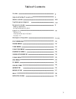
Page 2: ... Using the Remote Control Install TV Set your TV Connect Antenna and power Turn On TV PICTURE MENU SOUND MENU TUNE MENU FUNCTION MENU PARENT CONTROL CHANGE PASSWORD TV RATOMG OSD MENU PC MENU COLOR TEMP GEOMETRY RESOLUTION HELP SPECIFICATIONS 2 3 7 8 9 10 11 12 12 12 4 6 13 13 14 14 15 15 15 16 16 17 18 19 INSTALLATION ...

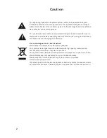
Page 3: ...ructions in the literature accompanying the appliance Correct disposal of this Product W aste Electrical Electronic Equipment WEEE Your product is designed and manufactured with high quality materials and components which can be recycled and reused This symbol means that electrical and electronic equipment at their end of life should be disposed of separately from your household waste Please dispo...

Page 4: ... only To reduce the risk of electric shock do not perform any servicing other than that contained in the operating instructions unless you are qualified to do so 19 Do not place any sources of danger on the apparatus e g liquid filled objects lighted candles 20 Wall or Ceiling Mounting The appliance should be mounted to a wall or ceiling only as recommended by the manufacturer ...

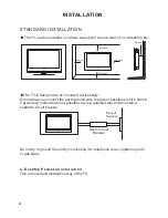
Page 5: ...vent possible electric shock if grounding methods are not possible have a qualified electrician install a separate circuit breaker Do not try to ground the unit by connceting it to telephone wires lightening rods or gas pipes a Desktop Pedestal Installation This is the default installation way of the TV 10inches 10inches 10inches 10inches 10inches Power Supply Short Circuit Breaker INSTALLATION 4 ...

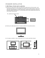
Page 6: ...the position of the wall brackets bolts as follow picture The actual dimension of the wall brackts bolt should according to the products 2 Remove the table stand of the TV when install the TV on a wall as follow 3 For proper ventilation allow a clearance of 10 on each side from the wall The wall brackets bolt position b Wall Mount Horizontal installation 100mm 100mm Four Mounting Holes Size M4 Scr...

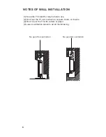
Page 7: ... the TV stand for may be future use 2 Don t set the TV set on shelves carpets beds or closets 3 Don t cover the TV with curtain or paper 4 Leave ventilation space to avoid the following No good for ventilation No good for ventilation 6 ...

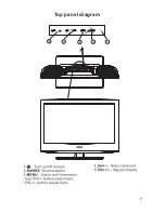
Page 8: ...7 Top panel diagram ...

Page 9: ...s input VGA AUDIO VGA audio input ANT 75 ohm Connect the antenna to the antenna input HDMI Input Digital signal input from HDMI video connector YPbPr Color difference components input and relevant video input AV Output 16 Connect to Mains Adapter POWER DC IN 3 5mm 14 15 9 VIDEO R L VIDEO R L OUTPUT INPUT Y Pb Pr VIDEO R L S VIDEO HDMI 1 1 1 2 2 2 4A 16 ...

Page 10: ...xits from the menu or sub menu and menus and adjust XIT the system settings to your preference 13 MENU Allows you to navigate the on screen menus 14 Press to cycle through the different picture settings P MODE 16 S MODE Press to cycle through the different sound settings 15 Press to select the MTS mode for example Nicam MTS BTSC MONO STEREO eg VOL VOL CH CH Universal Remote Control code 007F 4 1 5...

Page 11: ...3 10 DC 12V 4A side indicator AV Input Output S Video Input AV2 Input Y Pb Pr Input VGA Input HDMI Input ...

Page 12: ...7 11 ...

Page 13: ...12 Press Menu to exit sub menu ...

Page 14: ...13 memory 2 In Advance item Press button to enter sub menu as below figure 2 1 2 2 3 4 OFF ...

Page 15: ...14 Empty C C8 G PG 14 18 Empty G 8 ANS 13 ANS 18 ANS 16 ANS G PG PG13 R NC17 X NONE ...

Page 16: ...15 CHANNEL ...

Page 17: ...16 ...

Page 18: ...17 1366 ...

Page 19: ...al Image or simulacrum The TV no response with the Remote NO Video In PC Mode Vertical twinkling PC Mode horizontal ripping PC Mode The screen is too bright or too dark PC Mode To cause double image or phantom if there has high building or high mountain round TV You can adjust image effect by manually operation consult instruction of vernier regulation or change the direction of external antenna I...

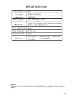
Page 20: ...E A V Ω Screen Size TV system Video system Input Output Power requirement Preset Channels Accessories User s manual Remote controller Power cord 2 x AAA Batteries 48W 3Wx2 NTSC M PAL M N NTSC PAL AIR 2 69 1 125 CATV Max power consumption 19 Audio output power 19 DC 12V 4A AC adaptor ...

Reviews: