UM-1096
Revision A
11
Chapter 4
General Operating Instructions
4.1
Introduction
Swiping a magnetic wand past the
Edit
key, from any of the
Data Display
screens, displays the
Main
Menu
. The
Up
and
Down
keys maneuver the selection bar up and down and
Edit
selects the highlighted
item to enter the sub-menus. All items with a sub-menu are indicated by a right facing arrow at the end
of the line. To edit menu item values, swipe the
Edit
key, and use the
Up
and
Down
keys to edit the
value. Once the desired value is entered, swipe the
Edit
key again to save the value. Swipe the
Next
key
to reverse out of a sub-menu.
Important
: Some values require a
Technician Sequence
to be entered to change their
values. This is to prevent the operator from inadvertently changing the values. When
prompted to “Enter technician sequence:” simply swipe the
Up
key four times to unlock the
value for editing.
4.2
General Setup for the SensePoint
After ensuring proper installation perform the following steps:
1.
Apply power to the gas detector
2.
Verify the detector has begun startup.
Note
: Once the detector is on the data screen, you may notice high or low values out of the full-scale
range. These values should quickly return to the zero-gas value if no gas is present. No false alarms
should be indicated at this time as the zero-gas value will be transmitted by the detector during the
user-defined warmup delay period (up to 5 minutes).
3.
Using the magnetic interface, navigate the menus to ensure:
a)
Alarm levels for Alarm 1, 2 and 3 are set to the desired value
Note
: SensePoint gas detectors have standard relays, which should also be set up at this time. When no
relays are installed, alarms are indicated only by the display color.
b)
Time and date are set correctly
c)
Engineering units are set to the desired value
d)
Calibration span gas value is set to the value of the calibration gas that will be used to
perform initial calibration
e)
Calibration marker is set to the desired value (this is the value the output will be held at
during calibration and the calibration purge delay)
4.
After sensor has stabilized, perform routine sensor calibration in accordance with
!
Summary of Contents for 10-0517
Page 4: ...UM 1096 Revision A III Drawings 44...
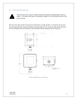
Page 10: ...UM 1096 Revision A 5 Figure 2 Remote Sensor Enclosure Mounting Dimensions...
Page 26: ......
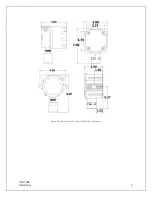
Page 49: ...UM 1096 Revision A 44 Appendix 9 Drawings Drawings Figure 13 Mounting Dimensions...
Page 50: ...UM 1096 Revision A 45 Figure 14 10 0517 CPU Board Figure 15 10 0533 I O Board...
Page 51: ...UM 1096 Revision A 46 Figure 16 10 0532 Modbus Relay Board...

