


UM-1096
Revision A
14
Chapter 5
Calibration Procedure
5.1
Preparation
Calibration is the most important function for ensuring correct operation of the SensePoint Series of gas
detectors. The CAL MODE is designed to make calibration quick, easy and error free, and a successful
Zero and Span calibration requires only four keystrokes. The 4-20mA output transmits 3mA during the
calibration, and 4mA during calibration purge to prevent alarms. After 5 minutes of inactivity the gas
detector will exit calibration mode automatically.
RC Systems recommends performing calibrations
Immediately prior to placing a gas detector in service
Any time a new sensor is installed
Every six months for routine calibrations (more often if sensor is known to have been
exposed to gas for extended periods of time)
Periodic bump tests are recommended if detector has potentially been exposed to
incompatible gases to ensure correct operation
Follow these calibration guidelines to ensure proper operation of your RC Systems, Inc. gas
detector:
Calibration accuracy is only as good as the calibration gas accuracy. RC Systems
recommends calibration gases with National Institute of Standards and Technology (NIST)
traceable accuracy to increase the validity of the calibration.
Do not use gas cylinders beyond their expiration date.
Calibrate a new sensor before it is put in use.
Allow the sensor to stabilize before starting calibration.
Calibrate on a regular schedule. RC Systems recommends once every 6 months, depending
on use and sensor exposure to poisons and contaminants.
Calibrate only in a clean atmosphere, free of background gas.
Summary of Contents for 10-0517
Page 4: ...UM 1096 Revision A III Drawings 44...
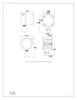
Page 10: ...UM 1096 Revision A 5 Figure 2 Remote Sensor Enclosure Mounting Dimensions...
Page 26: ......
Page 49: ...UM 1096 Revision A 44 Appendix 9 Drawings Drawings Figure 13 Mounting Dimensions...
Page 50: ...UM 1096 Revision A 45 Figure 14 10 0517 CPU Board Figure 15 10 0533 I O Board...
Page 51: ...UM 1096 Revision A 46 Figure 16 10 0532 Modbus Relay Board...