background image

P. 33

Agility

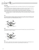
"Agility".will.keep.the.locked.in.heading.no.matter.how.much.the.wind.blows.or.the.torque.of.the.motors.change..The.only.time.the.RC.EYE.

650 will yaw left or right is when you give it a command to do so.

flIght oPerAtIon

14. 

Before switching the transmitter on, set the throttle stick to “motors off” and all trim levers / trim sliding controllers of 

the pilot stick to the neutral position. otherwise, the rC eye 650 may not recognise the transmitter after the battery is 

connected. 

Switch on the remote control. 

1. 

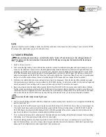
Then.connect.the.flight.battery..The.RC.EYE.650.then.performs.a.short.self-test.after.which.the.green.LED.is.permanently.lit..In.case.

2. 

of.an.error,.the.LEDs.flash..If.an.error.occurs,.the.rechargeable.battery.should.be.disconnected.and.connected.again.after.the.error.is.

eliminated (e.g. throttle not in zero position). In case of an error, the motors cannot be started again for safety reasons. Ensure that the 

RC.EYE.650.stands.as.levelly.as.possible.when.the.rechargeable.battery.is.connected..Until.the.green.LED.lights.up,.all.sensors.are.

being.internally.aligned.and.the.RC.EYE.650.should.not.be.moved.during.this.time..If.the.place.of.take-off.is.uneven,.it.is.recommended.

that.you.level.out.the.surface.and.save.the.neutral.position.through.full.throttle/yaw.right.(see.chapter.“set.neutral.position”).
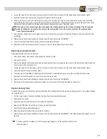
Start.the.motors.(with.throttle.on.zero,.yaw.left).and.let.the.motors.run.at.idling.speed..Check.the.running.of.the.propellers.once.again..

3. 

All.propellers.should.run.smoothly.on.one.level.without.the.RC.EYE.650.vibrating..If.a.motor.does.not.start,.turn.the.motors.off.again.and.

move.the.propeller.of.the.non-starting.motor.to.a.quarter.rotation.with.your.hand..Then.start.the.motors.again.
Ideally,.now.slowly.increase.the.speed.of.the.propellers.(the.throttle).of.the.RC.EYE.650.until.you.can.see.a.slight.increase.of.altitude..

4. 

Test.the.roll.and.yaw.directions.just.before.the.RC.EYE.650.starts.to.hover.to.ensure.that.the.transmitter.is.correctly.set.and.there.is.no.

channel inverting (control signals are reversed). Generally avoid any fast and big controlling motions. Also watch closely to see whether 

and.in.which.direction.the.RC.EYE.650.moves..By.using.trimming.on.the.remote.control,.you.can.prevent.undesired.movements

Never take off with a badly trimmed flight device.

Then.increase.the.throttle.until.the.RC.EYE.650.is.at.least.one.metre.above.the.ground..Carefully.try.to.correct.a.gentle.drift.with.the.trim.

5. 

levers.for.yaw,.nick.or.roll.
As.soon.as.the.RC.EYE.650.is.high.enough.in.the.sky,.decrease.the.throttle.until.the.RC.EYE.650.hovers..Now.you.have.managed.the.

6. 

critical.part.and.can.slowly.and.carefully.better.familiarise.yourself.with.the.throttle.controlling.motions.of.the.RC.EYE.650..To.land.the.

RC.EYE.650.again,.decrease.the.throttle.slightly.until.the.RC.EYE.650.gravitates.to.the.ground..A.somewhat.solid.touchdown.on.the.

ground.is.no.problem.and.should.not.be.corrected.with.jerky.throttle.movements.
Try.to.touch.down.where.possible.in.vertical.position.(“helicopter.landing”)..Avoid.landing.with.high.horizontal.speeds.(“airplane.landing”)..

7. 

After.landing,.turn.off.the.motors.(press.throttle.stick.to.the.bottom.right)..
Practice.this.starting.procedure.a.few.times.to.get.a.feel.for.the.RC.EYE.650..As.soon.as.you.are.reasonably.sure,.you.can.begin.to.

8. 

steer.the.direction.with.yaw,.nick.and.roll..Always.steer.slowly.and.carefully.and.practice.the.processes.a.little.before.trying.a.new.flight.

manoeuvre..The.first.flights.should.not.last.longer.than.30.to.60.seconds.each.

Summary of Contents for 88001RC

Page 1: ...Operating instructions 09 11 No 88001RC The picture is for reference only...

Page 2: ...eable batteries 9 7 Overview 11 8 Assembly 12 9 Configuration 24 10 Preflight preparation 28 11 Safety measures 29 12 LED indications 30 13 Before first take off 31 14 Flight operation 33 15 Maintenan...

Page 3: ...w the operating instructions to preserve this condition and to ensure safe operation These operating instructions relate to this product They contain important notices on commissioning and handling Pl...

Page 4: ...Therefore ideal flying conditions are when there is a complete lack of wind or very gentle and even wind The lightweight body frame and synthetic components are sturdy and enable excellent flight han...

Page 5: ...ables c 8 pole FFC FPC connector I x 2 Battery cord and attached connector x 1 II 10 pin flat cable with connector III x 1 Box 2 Driver system Aluminium profile with brushless motor and connection a w...

Page 6: ...II Magic tape for the stabilizer 150 x 20 mm red x 1 III Magic tape with adhesive tape at the back x 1 IV Pad for the stabilizer 12 x 12 x 3 mm black x 4 V Lock strap 210 mm x 2 VI Rubber band 12 7 c...

Page 7: ...it level i SPARE PARTS Spare parts Screws for the stabilizer 2 8 x 15 mm silver x 2 a Wave washer x 2 b Chassis screw 2 8 x 15mm black x 4 c Silicon tube yellow x 1 d Silicon tube red x 1 e Rubber rin...

Page 8: ...eration and protect it from any accidental use Safe operation can no longer be guaranteed if the product is visibly damaged is no longer working properly has been stored for extended periods in poor a...

Page 9: ...ging Before flying again these should be checked for possible tears or breakages Miscellaneous Consult an expert when in doubt about operation safety or connection of the device Maintenance modificati...

Page 10: ...immediately after use Always leave the LiPo flight battery to cool off first at least 10 15 minutes To charge LiPo rechargeable batteries always use a LiPo charger and a LiPo equalizer balancer Only...

Page 11: ...l 3 Battery cord with connector 4 Canopy 5 Spinner 6 Clockwise propeller 30 cm 12 7 Aluminium profile with brushless motor and connection wires mounted 8 Cap cover 9 Propeller 30 cm 12 10 Landing gear...

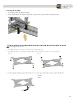
Page 12: ...ront 1 Connect the two motor driver boards QC1 42 Box 1 b to the Combined flight control board QC 09 QC 07 Box1 a with the 8 pole 2 FFC FPC connectors Box 1 c I Note the orientation of the board the b...

Page 13: ...pper and lower part of the boards In the below illustration the black arrow is indicating the front direction If the PCBs are not installed as described the programmed rotating directions will no long...

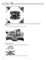
Page 14: ...Box 2 a into the bottom body frame 1 After the insertion rotate the profile by 90 in the reverse direction such that the motor is facing upward and the aluminium profile is 2 fitting into the bottom...

Page 15: ...motors with the male bullet connector to the closest female bullet connector from the motor driver boards QC1 42 Box 1 b in an anti clockwise direction The wires are of three colours connect the wire...

Page 16: ...ce the RC EYE 650 upside down on a stable platform 3 Drill bores on the chassis Box 3 d for mounting the plastic landing gear Before drilling mark the position of the bores with the landing 4 gear If...

Page 17: ...e screws for the slider plate Box 3 f III if you are using it to mount 7 the RC Logger HD HD 2 PRO Clip the camera mounting bracket Box 3 i I to a RC Logger HD HD 2 PRO Slide them into the slider plat...

Page 18: ...ing the landing protection rubber Remove a cap from one end of a carbon fibre 1 2 3 Insert a landing gear into a landing protection rubber Box 4 h Observe the correct orientation 2 Observe the orienta...

Page 19: ...e the aluminium profile to fit into the buckle These actions will damage the plastic buckle Peel off the protective films from the surfaces of the aluminium stabilizer Box 3 f 3 Peel off the protectiv...

Page 20: ...9 Ground Negative Contact 10 5 V Positive C1 R9 R13 R10 R14 R3 R7 R11 R15 4 R 8 R 2 1 R 6 1 R C6 ST3 ST1 1 2 5 6 ST2 1 2 3 4 5 6 7 8 9 10 The signals of the 8 inputs channels 1 8 are measured and pro...

Page 21: ...consists a long antenna you may insert it into the PVC tube for antenna Box 4 f And then insert the PVC tube for the antenna into the antenna holder on the bottom body frame Battery installation The u...

Page 22: ...E 650 may run out of control Loss of guarantee warranty Use the lock straps Box 3 h V provided to fasten the battery on the stabilizer 5 Assembly of the canopy Put the canopy Box 3 c on top of the sta...

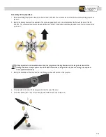
Page 23: ...clockwise propellers Box 2 d are marked with the word LEFT If the propellers are not installed as described the programmed rotating directions will no longer be in line with the rotating directions o...

Page 24: ...y choose the configuration of the control lever according to your use however it is recommended that beginners follow the recommended examples Ex factory the RC EYE 650 is configured to mode 2 The exa...

Page 25: ...The example given shows the procedure using a remote control in mode 2 If you prefer to use another mode the axes used may differ see chapter Possible flight modes Also ensure that the sliding control...

Page 26: ...t there for at least one second 1 The RC EYE 650 thus recognises the Nick channel and memorises this Move the Nick lever back to neutral position continue to leave 2 the THROTTLE on zero As confirmati...

Page 27: ...2 during a flight operation As confirmation the green LED LD1 lights up 3 Do not disconnect the rechargeable battery before the green LED LD1 lights up The settings will not be saved Disconnect the re...

Page 28: ...full deflection To set the modes Beginner Switch off DIP 1 and 2 Sport Switch on DIP 1 and switch off DIP 2 User Switch off DIP 1 and switch on DIP 2 For the user flight mode you must configure your o...

Page 29: ...e Please refer to your transmitter manual for programming details Safety measures 11 The RC EYE 650 has a range of safety measures which protect the model from damage and or should reduce possible dam...

Page 30: ...650 After successful alignment has taken place the red LED LD2 goes off and the green LED LD1 is permanently lit Adjustment of the Neutral Position If an adjustment to the neutral position is carried...

Page 31: ...r nick changes and or external influences e g side wind A gyro with heading hold function has a holding action against these tipping motions Both systems respond to a control command e g yaw to the le...

Page 32: ...rienced which may affect the RC EYE 650 A quicker response to the controlling motions and slight swerving of the RC EYE 650 forwards backwards or to the side may result from this Yaw Yaw denotes the r...

Page 33: ...rotation with your hand Then start the motors again Ideally now slowly increase the speed of the propellers the throttle of the RC EYE 650 until you can see a slight increase of altitude 4 Test the ro...

Page 34: ...here are any fine tears or grazing in the propeller Due to the high speed material parts could come loose if the propellers are damaged and this could lead to damage to or endangerment of the environm...

Page 35: ...m the faulty motor 1 Remove the canopy 2 Remove the stabilizer and the top body frame by loosening the screws Now you have free access to the motor driver board Detach the 3 bullet connector from the...

Page 36: ...error during zero compensation roll 1 x 300 ms on 300 ms off approx 1 sec off Gyro error during zero compensation nick 2 x 300 ms on 300 ms off approx 1 sec off Gyro error during zero compensation ya...

Page 37: ...ct is forbidden to be disposed via the domestic refuse The chemical symbols for the respective hazardous substances are Cd Cadmium Hg Mercury Pb Lead You can return used batteries rechargeable batteri...

Page 38: ...P 38...

Page 39: ...P 39...

Page 40: ...ding translation reserved Reproduction by any method e g photocopy microfilming or the capture in electronic data processing systems require the prior written approval by the editor Reprinting also in...

Reviews: