RBC Bioscience MagCore HF16Plus Engineer In Training Manual Download Page 2

1

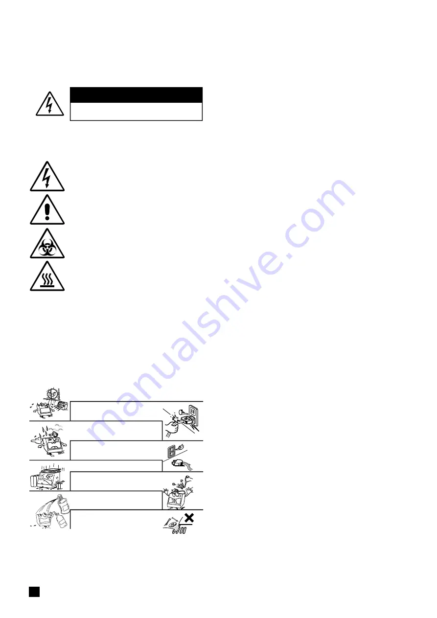
 Handle the power cord carefully.

Hold the plug when unplugging the cord.

Keep the set free from moisture, water, and dust.

Unplug the power cord when not using the set for 

long periods of time.

Do not obstruct the ventilation space.

Do not let foreign objects in the set.

Do not let insecticides, benzene, and thinner come in 

contact with the set.

Never disassemble or modify the set in any way.

 Avoid high temperatures.

Leave space for sufficient heat dissipation during the installation.

CAUTIONS 

Risk Of Electric Shock Do Not Open

Safety Precautions

Before use

WARNINGS and CAUTIONS stated below are intended to ensure safe operation, please follow them carefully.

CAUTION:

Do not remove the covers to reduce the risk of electric shock. Refer to the qualified 

service technician for replacement of any inner parts. 

CAUTION:

1. Handle the power supply cord carefully

Do not damage or twist the power supply cord. Damaged or twisted cord may 

cause electric shock or malfunction when used. When you remove it from the outlet, 

be sure to remove by holding the plug and not by pulling the cord.

2. Do not open the top cover

In order to prevent electric shock, do not open the top cover.

3. Do not place anything inside

Do not place metal objects or spill liquid inside the MagCore

®

 System and wipe 

away all spilled liquid to minimize the risk of system error and electric shock.

Note On Use:

1.  Read Instructions

 – All the safety and operating instructions should be read before operating 

the instrument. 

2.  Keep the Instructions 

– Please keep the safety and operating instruction manual for future 

reference. 

3.  Cautions and Warnings 

– All warning signs should be attached on the product and shown 

in the user's manual.

4.  Follow Instructions

 – All operating instructions should be followed.

5.  Cleaning

 – Unplug this product from the wall outlet before cleaning. Use only 75% of  EtOH to 

clean the surface of instrument.

6.  Attachments

 – Do not attach anything on the instrument. 

7.  Liquid and Moisture

 – Do not use this product near water and avoid moist areas.

8.  Accessories

 – Do not place this product on an unstable cart, stand, tripod, bracket, or 

table. The product may fall and cause serious injury to a child or adult, and serious damage 

to the product. Use only with a cart, stand, tripod, bracket, or table recommended by the 

manufacturer, or sold with the product. Any mounting of the product should follow the 

manufacturer’s instructions, and should use a mounting accessory recommended by the 

manufacturer.

9.  Ventilation

 – Slots and openings in the cabinet are provided for ventilation, which is required 

for safe operation as it minimizes the risk of overheating. This product should be placed on 

a hard surface to ensure proper ventilation. This product should not be placed in a built-in 

installation such as a bookcase or rack unless instructed by the manufacturer. 

10. Power Sources

 – This product should be operated only from the type of power source 

indicated on the marking label. If you are not sure of the type of power supply at your lab, 

consult the seller or local power company. For products intended to operate from battery 

power, or other sources, refer to the operating instructions.

11. Grounding or Polarization

 – This product may be equipped with a polarized alternating-

current line plug. This plug will fit into the power outlet in one way only. This is a safety feature. 

If you are unable to insert the plug fully into the outlet, try reversing the plug. If the plug should 

still fail to fit, contact your electrician to replace your obsolete outlet. Do not defeat the safety 

purpose of the polarized plug.

12. Power-Cord Protection

 – Power-supply cords should be routed so that they are not likely to 

be walked on or pinched by items placed near or against them. Pay extra attention to plugs, 

convenience receptacles, and the connecting point where the cord extends out of the product. 

13. Lightning

 – Unplug the product if it will not be used again for a long period or in the case of a 

heavy storm. This will prevent damage to the product due to lightning and power surges. 

14. Overloading

 – Do not overload wall outlets, extension cords, or integral convenience 

receptacles as this can result in a risk of fire or electric shock. 

15. Object and Liquid Entry


– Never push objects of any kind into this product as they may touch 

dangerous voltage points or short-out parts that could result in a fire or electric shock. Never 

spill liquid of any kind on the product.

16. Servicing

 – Do not attempt to repair this product by yourself. Refer all servicing to qualified 

service technician. 

17. Damage Requiring Service

 – Unplug this product from the wall outlet and refer servicing to 

qualified service personnel under the following conditions:

a)

 When the power-supply cord or plug is damaged,

b) 

If liquid has been spilled, or objects have fallen into the product,

c) 

If the product has been exposed to rain or water,

d)

 If the product does not operate normally  following the operating instructions. Adjust only 

those controls that are mentioned on the operating instructions for an improper adjustment 

of other controls may result in damage and will often require extensive work by a qualified 

technician to restore the product to its normal operation, 

e)

 If the product has been dropped or damaged in any way, and

f)

 When the product exhibits a distinct change in performance 

– this indicates a need for service.

18. Replace Parts 

– When replacement of parts is required, be sure that the service technician 

uses replacement parts specified by the manufacturer or those with similar features as the 

original part. Unauthorized substitutions may result in fire, electric shock, or other hazards.

19. Safety Check

 – Upon completion of any service or repairs to this product, ask the service 

technician to perform safety checks to confirm that the product is in proper operating 

condition.

20. Heat

 – The product should be situated away from heat sources such as radiators, heat 

registers, stoves, or other products that produce heat.

General Warning

Warning: Biological Hazard

Warning: High Temperature

Warning: Electricity

SAFETY INSTRUCTIONS

Summary of Contents for MagCore HF16Plus

Page 1: ...Ver 2020 09 10 04 ...

Page 2: ...ed on the marking label If you arenot sure of thetype of power supply at your lab consult the seller or local power company For products intended to operate from battery power orothersources refertotheoperatinginstructions 11 Grounding or Polarization Thisproductmaybe equipped with a polarized alternating currentlineplug Thisplugwillfitintothepoweroutletinonewayonly Thisisasafetyfeature Ifyouareun...

Page 3: ...50 60Hz Dimension W760xD710xH770 mm W27 95xD29 92xH30 31 inches NetWeight 76 5kg 168 68LB MagCoreSuper 68 5kg 151LB MagCoreHF16Plus Specification Operating Parameters Operating Environment Applications Applications Applications Whole Blood DNA 200µl 400µl 1 200µl Viral Nucleic Acid DNA RNA 200µl 400µl 1 200µl FFPE Genomic DNA Forensic DNA Plasma and Circulating Cell Free DNA 1 200µl Tissue Genomic...

Page 4: ...tcartridge 16 EmergencyStop 17 StartPrograms 18 Ifthe testresultoftheopticmeasurementisoverdetection 19 Stop 21 Enable thebarcodefunction 21 Barcodescanningandediting 22 Optic data 22 Easymaintenance 23 ReplaceO Ring 23 PistonTest 23 Clean PiercingNeedles 25 RejectTip 25 Heater Test 26 Optic Test 26 UVsterilization 27 AlarmHistory 27 SystemStatus 28 Update Program 29 Clean theWasteBox 29 Replaceth...

Page 5: ...or ofthebase 57 Replace PCB 58 Replace PLC 59 Replace PowerSupply 60 Replace Touch Panel 61 Replace Printer 62 Electricalcontrolandengineeringsoftware 63 System 64 Parts 65 Mainboardconfiguration 66 PLCconfiguration 67 Copy theengineeringsoftwareto thedesktop 68 Installthe HMI updating software 68 Create anuploadingfolder 69 Installthe driver 70 HMIupdating 72 PLCupdating 73 Position TeachingTools...

Page 6: ... O Rings X 16 7 EmptyCartridge X10 8 SampleTube Elution TubeX 20 9 PipetteTip X 20 10 MagCoreCuvetteSet 10pcs X 1 11 Waste BoxX1 12 BarcodeScannerX1 MagCoreSuperOnly 1 2 3 4 5 7 6 8 9 10 11 12 You can purchase Cat No MSC100 MagCore Cuvette Set X100 from the local distributor MagCore Super Only MagCore HF16 Optional Specification ...

Page 7: ...6 RBCBioscience BeforeInstallation Installation Please refer to the machine size shown in the above figure to prepare an appropriate position for the machineand reserve spaceforheat dissipation ...

Page 8: ...7 IQ Documents IQ OQ PQ Documents ...

Page 9: ...8 RBCBioscience OQ Documents ...

Page 10: ...9 PQ Documents ...

Page 11: ...10 RBCBioscience System Overview Slots There area total of16slots number1 16 fromleft to right 1 234 56 789 10 11 12131415 16 ...

Page 12: ...11 ModulePositionDescription Liquid handling module Work platform Heating module Optic module Super Only Frame Gantry structure ...

Page 13: ...12 RBCBioscience Unpacking PrepareUnpackingTools Ifthecargoisdamaged White Red Ifthecargoisupsidedown Sliver Red 2 PhillipsScrewdriver 1 HexWrench 3mm 3 Scissors ...

Page 14: ...e HF16 Plus Super Proceedinstallationproceduresafterplacingtheinstrumentonasolidbench top 1 Usescrewdriverstoloosenthescrewsasshowninthepicture 2 Removetheredfixingplates 3 Saveallthematerialsformaintenanceforfutureuse ...

Page 15: ...apterforthe informationabouttheoperation PleaserefertoP 23 Step3 Testheater PleaserefertoHeaterTestchapterforthe informationabouttheoperation PleaserefertoP 26 Step4 Testopticmodule MagCore SuperOnly PleaserefertoOpticTestchapterforthe informationabouttheoperation Whentheopticmoduletestisfinished please comparetheresultwiththereferencesheet tomakesuretheopticmoduleisfunctioning properly Pleaserefe...

Page 16: ...atus ending time andtest report of the machine Theabovefigureshows the function listof theoperation screen and the description ofthestatusicons Start Barcode Maintenance Optics Executethe extractionprocess Easymaintenanceand systemsettings Opticsdatabrowsingand outputfunctions MagCoreSuperonly Barcodescanning editing printing functions optionalforMagCoreHF16 Plus ...

Page 17: ...isunidirectional Itisnotpossibleto putitintothewellifthedirectionisnotcorrect 2 Putthe200μlSPtipintotheW4oftheT Rack Pleaseinsertthefrontendofthecartridgeintothespace belowthefixingplateoftheCartridgeRack 1 Putthetipintothecorrespondingwellaccordingtotheleft figure 2 PuttheT Rackintothemachine PleaseinstalltheTipandTube accordingtotheinstructionsonthe extractionkitusermanual PleaseinserttheCartrid...

Page 18: ...security information to correctly stop the machine whenanaccidenttakesplace When an emergency situation occurs and the machine is still running please press the stop button or open the door of the machine to stop themachineimmediately ...

Page 19: ... instructionsontheMagCore extractionkituser manualandputconsumablesintothemachine PressStarttogotothenextstep Systemwillaskyouwhetherornottoscanthe barcode Ifthereisabarcoderecordfromprevioustest processes thesystemwillaskyouwhetherornot todeletethepreviousbarcoderecord Ifthereis nobarcoderecord thesystemwillnotaskyou MagCoreSuperonly optionalforHF16Plus Start Programs Thenumbercanbe foundinthesti...

Page 20: ...rtotheopticdatachapter f A Pleaserecordandsavethe currentmeasureddata PleaseselectYES Pleasecheckthevalueofeachsample If thereisavalueshowingDNA 300ng μlorRNA 240ng μl pleaserecord thenumberofthesample Itmeansthe sampleneedstobediluted Afterrecording thenumberoftheslot pleaseinsertthe USBFlashDriveandpresstheSavebutton tosavetocurrentmeasureddata After finishingtheabovesteps pleasepressNext Step 1...

Page 21: ... values 1 InserttheUSBFlashDriveandthen presstheSavebuttontosavethe currentmeasuredvaluesaftertheUSB iconshowsinthestatusbar Please takeouttheUSBFlashDriveand youcanperformotheroperations aftertheiconofUSBFlashDrive disappears 2 Thefilesavedlasttimeandthistime willbekeptinthemachine Ifthefilesavedlasttimeislost you canretrievethisfileaccordingtothe instructionsinoptictestdatachapter Pleasesavethed...

Page 22: ...r TheBarcodefunctionisenabled Enablethebarcodefunction 1 2 3 MagCoreHF16PlusOnly Duringthetestprocess pleasepresstheStop buttonifyouwanttopause PleasepresstheAbortbuttonifyouwanttoend thetest Thetestisaborting andthemachineisreturning totheinitialposition Pleasedonotoperatethe machineduringtheprocess Themachinehasbeenstoppedandreset please presstheOKbuttontogobacktothemainmenu Stop 1 2 3 4 ...

Page 23: ...tabuttoninthemain menu OpticsDatamainmenu Themachinewillautomaticallysavetwobatchesof datainthememory Savefile InserttheUSBFlashDriveandthenpressthe Savebuttontostorethecurrentmeasured valuesaftertheUSBiconshowsinthestatus bar PleasetakeouttheUSBFlashDriveand youcanperformotheroperationsafterthe iconofUSBFlashDrivedisappears PleaserefertotheSystemOverviewchapterforthe informationaboutthenumbersoft...

Page 24: ...piston is smooth attakingallthreetypesoftipsfromtheT rack PleaseselectthePistonTestbutton ReplaceO Ring Piston Test Easymaintenance 2 1 Easymaintenanceincludesthemaintenances whichneedtobedonebyusers Theseitems includesterilization clearing simpletestanderror messagereport etc Usersmustperformthese itemsperiodicallytoensurethesystemisfunctioning properly Maintenance Please perform the Piston Test ...

Page 25: ...leaseadd1mlwatertotheSampleTube andputitinW1oftheT Rack 3 PleaseselectTestW3Tip 4 Pleasecheckwhethertheliquidlevelsare consistentwitheachother Iftheliquidlevels arenotconsistentwitheachother please checktheO Ring PleaserefertotheReplaceO Ring chapterformoreinformation C TesttheTipoftheW4 MagCoreSuperOnly 1 Pleaseputthe200μlSPTipintoW4ofT Rack 2 Pleaseadd1mlwatertotheSampleTube andputitinW1oftheT R...

Page 26: ...ecloth If the system is stopped from power shortage or other abnormal conditions and the tips are still on the pistons you haveto press RejectTip to remove thetipsfromthepistons PleaseselecttheRejectTipbutton Clean Piercing Needles 2 1 1 Warning ThetipsofthePiercingNeedles areextremelysharp Please cleanthemcarefully ...

Page 27: ...totheInstallMagCore Cuvette chapter PleaseselectOpticTest PleaseselecttheEmptyCuvetteandthenwaitfor 15minutestoperformthetest Thetestmaytakesometimetowaitforthe D2lamptoprewarm Thescreenwillshowthe measuredvaluesafterthetestisfinished You caninserttheUSBFlashDriveandpresstheSave buttontostorethecurrentdataaftertheUSBicon showsinthestatusbar PleasetakeouttheUSB FlashDriveandyoucanperformotheroperat...

Page 28: ...taaftertheUSBicon showsinthestatusbar PleasetakeouttheUSB FlashDriveandyoucanperformotheroperations aftertheiconofUSBFlashDrivedisappears Alarm History PleasesavethedataintheUSBFlashDrive andtransfertocomputer orthedatain theUSBFlashDrivemaybeoverwritten later Filename AlarmHistory cvs UV sterilization PleaseselecttheUVbutton Pleaseselectthesterilizationtime Warning The UV lamp is dangerous Please...

Page 29: ... Serial Optical module serial number MagCore Super Only Power on Time The total time that the machine is powered on UV Lamp Used Time The used time of the UV lamp D2 Lamp Used Time The used time of the D2 lamp MagCore Super Only SelectSystemTimeSetuptosetupthesystem timeofthemachine Setupthesystemtime Pleaseinputthelocaldateandtime thenpressthe Updatebuttontosave Youcanseethetimethat youchangedin ...

Page 30: ...FlashDriveintotheUSBPortofthe machine Pleasepress UpdateProgram after theUSBiconappearsinthestatuslist PleaseselectYES Theupdateisfinished pleasepressOKtocheck whethertheUIversioniscorrect Pleaseremovethewastewhentheprogramis completedandwashthewasteboxeveryday Warning Pleaseconfirmthenameof UIversion Iftheversionisnot correct pleaseexecutethe updateprogramagain ...

Page 31: ... figureandthenclosethecoveroftheprinter If the position of the thermal paper roll is not correct thered yellow lamp will flash Pleasepress the Feed button to confirm if the replacement is correctlydone Replacethermalpaper Replacefuse 250V5A Please use the specific fuse If you usethefusewithhigherspecification themachinemaybeburned You can purchase the Cat No MSP005 Thermal Paper from the local dis...

Page 32: ...advanced machine calibration Only trained engineers can perform the above operations Advanced maintenance Recommended frequency for maintenance Frequency of use Maintenance cycle Less than 20 times a month 1 Year 1 to 3 times daily Six months More than 3 times a day Three months ...

Page 33: ...32 RBCBioscience Turnoffthepowerandremovepowersocket beforeprocessingadvancedmaintenance Caution Caution Alladvancedmaintanencemustbeperformed bytrainedEngineers ...

Page 34: ...33 Disassemblethebackservice lid ...

Page 35: ...34 RBCBioscience Disassemblethetopservicelid ...

Page 36: ...35 Axisdirections V axis direction X axis direction Y axis direction C axis direction M axis direction ...

Page 37: ...ience ReplacetheUVlamp Open the front door 1 Switch off the power supply 2 Loosen the three screws of the protection metal sheet 4mm Hex wrench and take off the sheet 3 Replace the lamp and lock back all the parts ...

Page 38: ...en the front door 1 Unplug the wire connector of the LED 2 Loosen the three or five screws on the top of the piston module 3 mm Hex wrench and take off the LED module 3 Replace the LED light bar and lock back all the parts ...

Page 39: ...r 1 Loosen four screws of back service lid 2 Loosen four screws of optic service lid 2 Cut cable tie 6 places 3 Loosen three screws 4 Move the deuterium lamp to the right side 1 Open the back service lid 2 Loosen four screws on optic service lid MagCore SuperOnly ...

Page 40: ...e tray is exposed Use tools to remove connecting part on top of the tray until it is completely opened and cables can be easily removed Hold the base of the tray and twist it to the side to remove it Repeat on the other end of the tray 4 Disconnect the cables 5 Remove 4 screws if needed remove the motor to create more space for operation 6 Remove old power supply 7 Follow the steps in the reversed...

Page 41: ...e connector of the LED 2 Loosen the three screws on the top of piston module 3mm Hex wrench and take off the LED module 3 Screw off the eight screws on the acrylic nameplate at the front side 2 5mm Hex wrench 4 Screw off the four screws on the metal sheet 2 5mm Hex wrench ...

Page 42: ...ult pistons and replace with new pistons 2 5mm Hex wrench 8 Screw up the four screws 2 5mm Hex wrench 9 Screw up the screws above the piston 2 5mm Hex wrench 10 Reinstall the acrylic nameplate on the piston module and the LED lamp on the machine 11 After the above steps are finished please perform the Piston Test to check if the replacement is successful ...

Page 43: ... off the eight screws on the acrylic nameplate at the front side 3mm Hex wrench and take off the LED module 4 Screw off the four screws of the metal sheet 2 5mm Hex wrench 5 Screw off the three screws of the axle core of the ejector rod 2 5mm Hex wrench 6 Take out the ejector rods by pushing it downward 7 Replace the ejector rods and reinstall the ejector rod module back in order ...

Page 44: ...w off the four screws on the heating module 2 mm Hex wrench 2 Pull out the temperature probe from the module 3 Remove the connection wire to the heater 4 Remove the protection switch wire to the heater 5 Take out the heating module from the bottom 6 Install a new heating module and lock back all the parts ...

Page 45: ...efront door 1 Open the front door 2 Screw off one screw and one nut 4mm Hex wrench Note that you can only replace one gas spring at a time 3 Screw off the screw on the front door 3mm Hex wrench 4 Replace the gas spring and screw up the screws ...

Page 46: ...45 ReplaceDoor Sensor 1 Open the front door 2 Pull out the sensor 3 Disconnect the connector ...

Page 47: ...xissensors Open the front door and take out the waste box cartridge rack and T rack 1 Screw off the two screws on each sensor 2 5mm Hex wrench 2 Remove the wires connected to the sensors 3 Replace new sensors and screw up the screws ...

Page 48: ...47 Replacethesensorsof C V XandY axes 1 Remove the wires connected to the sensors 2 Screw off the two screws on each sensor 2 5mm Hex wrench 3 Replace the sensors and lock back all the parts V X Y C ...

Page 49: ...48 RBCBioscience ReplaceCoolingFans 3 Loosen two screws and remove protecting net ...

Page 50: ... to the X axis motor 2 Screw off the two screws on the holder of the motor 5mm Hex wrench 3 Screw off the two screws on the timing gear 1 5mm Hex wrench 4 Screw off the four screws on the motor 3mm Hex wrench 5 Replace the X axis motor 6 Install the new X axis motor on the machine ...

Page 51: ... four screws on the metal sheet of the Y axis motor 3mm Hex wrench 4 Screw off the two set screws on the timing gear 2 mm Hex wrench 5 Screw off the four screws on the motor 3mm Hex wrench 6 Replace the Y axis motor 7 Install the new Y axis motor on the machine 8 Note that the belt should have always some tension when reinstalling it 9 Disassemble the Y axis fixing plate and screw off the two scre...

Page 52: ... 2 Screw off the four screws of the metal sheet of the Y axis motor 3mm Hex wrench 3 Push the metal sheet of the motor forward 4 Replace the timing belt 5 Install the Y axis motor on the machine 6 Note that the belt should be a little tight when reinstalling it 7 Disassemble the Y axis fixing plate and screw off the two screws Phillips screwdriver ...

Page 53: ...nnector of the LED 2 Loosen the three screws on the top of piston module 2 5mm Hex wrench and take off the LED module 3 Screw off the eight screws on the acrylic nameplate at the front side 2 5mm Hex wrench 4 Screw off the four screws on the reinforced metal sheet 1 5mm Hex wrench ...

Page 54: ...ion wire to the V axis motor 6 Screw off the four screws on the motor 3mm Hex wrench 7 Screw off the three screws on the axle sleeve 2 5mm Hex wrench 8 Replace a new V axis motor 9 Install the new V axis motor on the machine ...

Page 55: ... lamp driver 3mm Hex wrench 3 Screw off the two screws on the driven timing gear 4mm Hex wrench 4 Screw off the four screws on the motor 3mm Hex wrench 5 Screw off the two set screws on the timing gear 1 5mm Hex wrench 6 Replace the C axis motor 7 Install the new C axis motor on the machine 8 Note that the belt should be a little tight after installation ...

Page 56: ...e four screws on the optic lamp driver 3mm Hex wrench 3 Screw off the two screws on the driven timing gear 4mm 5mm Hex wrench 4 Screw off the four screws on the pressing metal sheet 3mm Hex wrench 5 Replace the C axis timing belt 6 Note that the belt should be a little tight 7 Reinstall the above components back in order ...

Page 57: ...the liquid container above the heating module 2mm Hex wrench 3 Screw off the two screws on the metal sheet of the motor 3mm Hex wrench 4 Screw off the two screws on the timing gear 2 5mm Hex wrench 5 Screw off the four fixation screws on the motor 2 5mm Hex wrench 6 Replace a new lift motor 7 Install the new lift motor on the machine 8 Note that the belt should be a little tight after installation...

Page 58: ...ting module 2mm Hex wrench 3 Screw off the two screws on the reinforced metal sheet of the motor 3mm Hex wrench 4 Screw off the two screws on the bearings at the lateral grooves 4mm Hex wrench 5 Screw off the four fixation screws on the fixation bases and move the drive module upward 3mm Hex wrench 6 Replace the timing belt 7 Note that the belt should be a little tight 8 Install the lift motor tim...

Page 59: ...58 RBCBioscience ReplacePCB PLC Power Switch PCB 1 Loosen four screws of top service lid 3 Loosen five screws of PCB 2 Disconnect the connector of PCB ...

Page 60: ...59 ReplacePLC 3 Loosen two fixed screws of PLC 2 Disconnect the connector of PLC 1 Loosen four screws on top service lid ...

Page 61: ...60 RBCBioscience ReplacePowerSupply 1 Loosen four screws on top service lid 3 Loosen four screws of power 2 Disconnect the connector of power 4 Loosen four screws ...

Page 62: ...61 ReplaceTouchPanel 1 Open the front door 2 Loosen two screws 3 Remove fixed block 4 Remove the HMI ...

Page 63: ...62 RBCBioscience ReplacePrinter 1 Open the front door 2 Loosen four screws 3 Close the front door 5 Take off the paper roll 4 Open the cover 6 Loosen three screws ...

Page 64: ...63 Electrical control and engineering software ...

Page 65: ...ne Interface SelectProgram CartridgeCode HMIsendtheprogramtoPLC andsendasignalthroughPCBtoallparts Main_Board OpticSpectrometer A260 A280 A320 PLCruns programs actions PLC ProgrammableLogic Controller ForExample HMI Win8 Program App PLC CPU ...

Page 66: ...ter Barcode Optic Spectrometer D2Lamp UVLamp HMI PLC Door XHome Up YHome VHome CHome MAxis HeaterandMagnet UpDown Temperaturesensingrod Heater YAxis DC24VPowerSupply PowerSwitch PowerCable VAxis XAxis CAxis Down I O ...

Page 67: ...66 RBCBioscience Mainboard configuration There are 2 types of PCBs in MagCore Super Old type and New type Please check your PCB type and refer to the corresponding configuration Old Type ...

Page 68: ...67 New Type PLC configuration ...

Page 69: ...6Install ToolSoftware tothedesktop 2 Openthefolderandselect EasyDownload_ v1 83 forupdatingPLC 3 Openthefolderandselect PM_2 0 5 11 for updatingHMI 1 Open PM_2 0 5 11 folder 2 Openthefile OemKeyV3_00 txt andcopy thekeyserialnumber 3 Select PMDesignerVersion2 0 5 11 to installthesoftware 4 Inputtheserialnumberin SerialNumber Copytheengineering softwaretothedesktop Install the HMI updating software ...

Page 70: ...eFiletocreatenewdata 3 Input Update attheprojectnamecolumn andpress Next 4 Selectaconnectingmethodandthenpress Next 5 Confirmthetransmissionparameterandpress Finish 6 Confirmthatthe newprojecthasbeencreated 7 SelectFile Exitandclosethesoftware Createan uploadingfolder ...

Page 71: ...l tomodify thesettings 3 Pleaseenterthe ControlPanel andselect hardwareandSound andthenselect Devicemanager 4 Select NEOHMI in OtherDevices 5 Select UpdateDriver atthe General subpage 6 Select Browsemycomputerfordriver software 7 Select Browse tosearchthe Program Files X86 inyourCdrivetofindthesub folder PMDesigner Install the driver ...

Page 72: ...71 8 Findthe V2 0 folderatthesub folder PM Designer andselect Usb folderatthe V2 0 folderandpress Confirm 9 Select Trustthesourceofthesoftware and installit 10 Theupdateisfinished ...

Page 73: ...ctHMItothecomputerbyaUSB transmissionwire 2 StartthePMDesignersoftware 3 Pressthedownloadicon 4 Selecttheprpfiletobeuploaded 5 Selectaconnectionmode 6 Starttobegintheuploadandfinishthe updating HMIupdating AMale BMaleUSBCable ...

Page 74: ...p andreplacetheconnectionwirewith thePLC RS232communicationconnection wire 4 Connecttoyourlaptop 5 PowerON 6 Openthe EasyDownload_v1 83 folderand open EasyClient software PLCupdating PLCRS232CommunicationCable Combinetwocables 1 2 Switch RUN to STOP DisconnectoriginalCableandchangeto PLCRS232 Cable 1 2 ...

Page 75: ...8 SelectaDVZfiletobeuploadedandpress Next 9 OpenCOMPort 10 Selectacommunicationmethodandclick Download tostartthedownload 11 Afterthescreenshows Download Completed pleaseselect Confirm to finishthedatatransmission Clickthe PLC xxxx dvz FileandClickthe Open ...

Page 76: ...75 12 PowerOFF 13 Reconnecttheoriginalconnectionwireand changetheswitchto Run tofinishthe installation 14 PowerON Disconnect PLCRS232Cable andchangetooriginal Cable 3 2 3 Switch STOP to RUN 2 ...

Page 77: ...76 RBCBioscience PositionTeaching Tools 200µlSPTip toolA toolB toolC PipetteTip ...

Page 78: ...nce 2 SelectVenderandinputpassword 3 SelectTeachPositionandentertheteaching page 4 Thewiringconfigurationontheconnectorof themotoronthemainboard DisconnectX Y CMotorPowerCable The pre operation before calibration X V Y C ...

Page 79: ...is andC axismotorsfromthemainboard Refertopage75 2 Putthe200μlSPTipsattheW4atthetwoendsoftheT rack 3 MovetheX axisandY axistothepositionwherethe200μlSPTipislocated X axiscalibration Pushitdownwardandinsertthepistonintothetip Movethepistontoalignwiththetip ...

Page 80: ...e andinputtheXEncodervalueshownatthetopside andthenselect LoadX EncodeCalculate 5 Select Yes toupdatethepositionoftheX axis 6 ReplugtheconnectorsofX axismotortothemainboard Inputnewvalue pulse Pressthe LoadXEncoderCalculate ...

Page 81: ...thepositionthatthepistontakeoutthePipetteTip andpressituntilthe pistoncompletelyinsertsintotheTip 4 Select InputYPulse andinputtheYEncodervalueshownatthetopside andthenselect LoadY EncodeCalculate 5 Select Yes toupdatethepositionoftheY axis 6 ReplugtheconnectorsofY axismotortothemainboard Y axis calibration Correct completelyinsertintothepiston Wrong doesnotcompletelyinsertintothepiston ...

Page 82: ...themainboard Refertopage75 2 Select CPositionPage atthe Teachposition pagetoentertheC axiscorrectionpage 3 InsertteachingtoolAintotheareabelowthefixationplugofthecartridgerack C axiscalibration 1 9 2 10 3 11 4 12 5 13 6 14 7 15 8 16 Holepositions MagcoreSuper Only ...

Page 83: ...dholdfortwoseconds CheckwhetherthevalueoftheCEncoderhasbeen writtenintotheCSlot01ontherightside 6 7 Performthecorrectionofallthe16holepositionsinorder 8 RemovetoolA BandCafterallcalibrationsarefinished 9 ReplugtheconnectorsofC axismotortothemainboard 1 2 19273 19273 ToolB InsertToolC InsertToolC C1 C2 C1 C2 C1 C2 CalibrateC1Position ...

Page 84: ...83 AutomaticOptical Measurement The optical module provides O D A260 and A280 measurement of individual samples O D detectionrange ABS 6 A320 Normalization Disposablecuvettes RBC Cuvette DeuteriumLamp ...

Page 85: ...oscience NG OK OpticalCalibration FlowChart EmptyCuvetteTestofstandardcuvette 1 Placethecuvetteintothecartridgerack Makesurethecuvetteisplaced straight Wheninstalling it pleasedo not scratch theoptictestwindow ...

Page 86: ...theflow chartaccordingtothecountvalue Wavelength Tolerance 260 nm 750 280 nm 1250 320 nm 1250 Standard CuvetteVaule If the value is out of tolerance range adjust the integration time as instructed on the next page Wavelengh Value 260mm 10172 280mm 20006 320mm 17944 Wavelengh Value 260mm 9158 280mm 19829 320mm 18786 Wavelength Value 260mm 10437 280mm 18107 320mm 17475 Wavelength Value 260mm 10291 2...

Page 87: ...timeby1min Ifthecountvaluesarelowerthantherange increasetheintegrationtimeby1min Press IntegrationTime toadjustthetime andpress Finishtocompletetheadjustment 3 Press Update tofinishtheadjustment 4 NotethatEmptycuvettetestshouldbe performedafterchangingtheintegrationtime Adjust integrationtime Wavelength Tolerance 260mm 750 280mm 1250 320mm 1250 ...

Page 88: ... Start to performdetection 6 Afterdetection removetheliquidinthe cuvette Centrifugebrieflyandremovethe residualliquid Put60μLstandardsolution intothecuvette Theliquidtransfershouldbe completedwithin5min Preparestandardsolutionaccordingtothe datasheetwhichcomeswiththeStandard ReferenceSet 7 Placethecuvettewithstandardsolutionback intothesamewellofcartridgerack Press Start tocontinuethesample detect...

Page 89: ...88 RBCBioscience ...

Page 90: ...the sensor 6 Y_SoftLimt Causes Manual Y JOG operation exceeds the distance programmed in the software Solutions 1 Alarm Reset 2 Manual Y JOG operation 7 Y_SoftLimt Causes Manual Y JOG operation exceeds the distance programmed in the software Solutions 1 Alarm Reset 2 Manual Y JOG operation 8 Y_Encode no change Causes No signal response from the Encoder Solutions 1 Replace the cable connected to th...

Page 91: ...he Encoder Solutions 1 Replace the cable connected to the Encoder 2 Replace the motor module 14 V_Position Over 60 Pulse Causes The position command coordinate is vastly different to the Encoder coordinate Solutions 1 Check whether the terminal of the PLC Y00 Cable has dropped off 2 Replace the cable connected to the power of the motor 3 Replace the main board 4 Replace the motor module 15 V_Home ...

Page 92: ... Replace the optical communication cable 3 Replace the PLC RS232 optical communication cable 4 Replace the optical module 27 Y_ Motor Hit Hard stop Causes When you perform the motor initialization the motor collides into a hard stop Solutions 1 Check whether the terminal of the PLC Y00 Cable has dropped off 2 Replace the cable connected to the power of the motor 28 V_ Motor Hit Hard stop Causes Wh...

Page 93: ...he motor 3 Replace the main board 4 Replace the motor module 20 X_Home Sensor Fail Causes When you perform the motor initialization the Home sensor has no response and the motor collides into a hard stop Solutions 1 Check whether the cable has dropped off 2 Replace the sensor 21 C_SoftLimt Causes Manual C JOG operation exceeds the distance programmed in the software Solutions 1 Alarm Reset 2 Manua...

Page 94: ... has dropped off 2 Replace the cable connected to the power of the motor HMI Communication Error Causes HMI PLC or the temperature controller has no response Solutions 1 Check whether the main board has damaged 2 Check whether the PLC RS485 and HMI R 485 Cable has dropped off 3 Replace the main board 4 Replace the PLC 5 Replace the HMI Code No Content Causes and solutions ...

Page 95: ...94 RBCBioscience ...

Page 96: ......

Page 97: ......

Page 98: ......

Page 99: ......

Page 100: ......

Reviews: