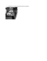
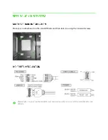
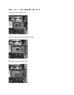
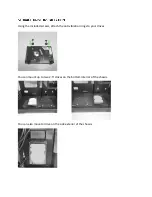
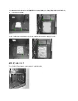
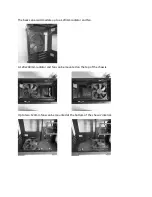
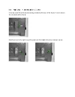
Place your motherboard on the standoff bolts and then lock it in using the included screws.
Please refer to your motherboard’s user manual on
where to install the IO cables for the
chassis.
Page 1: ...1 Remove the front panel using the bottom release handle 2 Open both detachable swivel glass doors and then lift up to remove them 3 Remove the top panel...
Page 2: ...4 Remove the accessories pack and untie the connectors...
Page 3: ...Place your motherboard on the standoff bolts and then lock it in using the included screws Please refer to your motherboard s user manual on where to install the IO cables for the chassis...
Page 4: ...Place your PSU inside the tray Use the included screws to hold it in place Plug the power cord to the PSU...
Page 5: ...g the included screws attach the anti vibration rings to your drives You can mount up to two 2 5 drives on the bottom interior of the chassis You can also mount a drive on the side exterior of the cha...
Page 6: ...the anti vibration rings between the mounting holes then slide the drive to hold it in place Then attach the included thumb screw beside the drive to keep it in place The front of the chassis interio...
Page 7: ...The back can accommodate up to a 120mm radiator and fan A 120x240mm radiator and fan can be mounted on the top of the chassis Up to two 120mm fans can be mounted at the bottom of the chassis interior...
Page 8: ...s panel for external watercooling is located at the rear of the chassis To start loosen the screw behind the chassis Slide the screw to the right to open the panel and then tighten the screw to keep i...
Page 9: ...tray and then insert the included screws from the bottom if you are using a 2 5 or from the sides if you are using a 3 5 drives Detach the 2 5 drive plate located at the left side of the chassis by r...