background image

Installation and Service manual

Compass STD 22

Compass STD 22 Compact

140

Edition: Sept. 13, 2005

3646/110--233.DOC010302

Serial

No.

Comments, Information

Indications

8

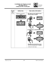
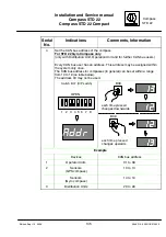
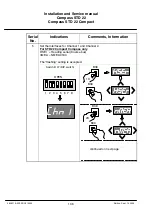
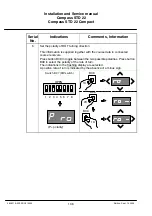
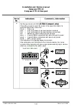
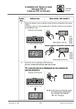
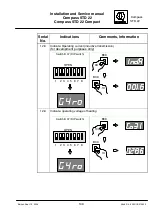
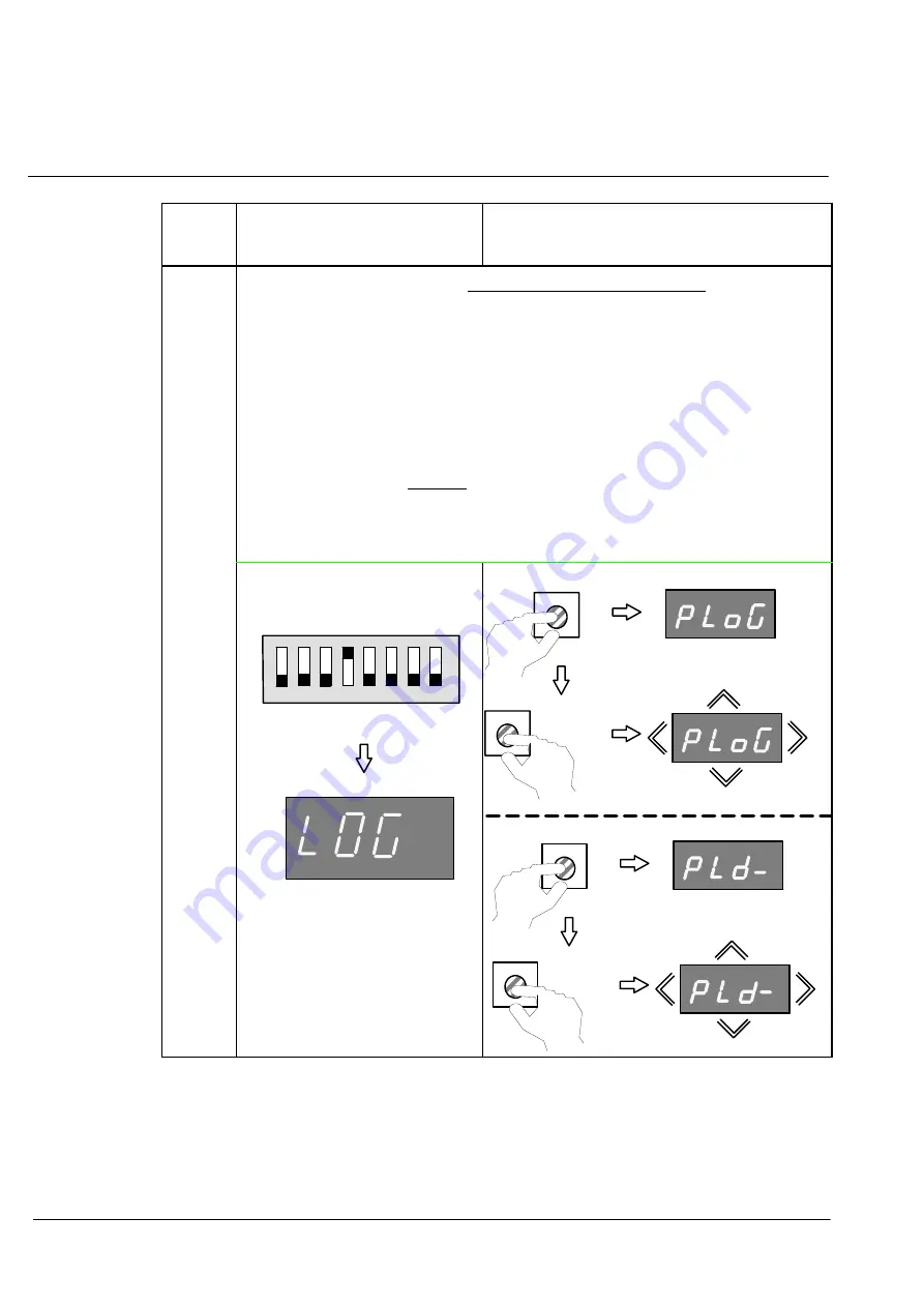
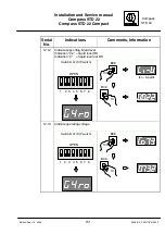
Set the speed source for SEC

(STD22 Compact only)

This setting is used to select the source of the speed information for

automatic Speed Error Correction.

PLoG =

Pulse Log

PLd-- =

Puls Log (polarity of the input interface inverted)

PLd

=

Puls Log (polarity of the input interface not inverted)

uhu.

=

NMEA Log (means water speed in general)

ubu.u =

means NMEA Log specified with speed through the water

ubu.G =

means NMEA Log specified with speed over ground

GLoG =

GPS--receiver speed

The indications in the flashing display are selected.
If the setting does not correspond to the connected device, the course

correction relay responds and gives an appropriate warning only to devices

which are connected to this alarm output.

Switch B 37 (DIP switch)

1 2 3 4 5 6 7 8

OPEN

B38

2X

B39

1X

B38

1X

B39

1X

Summary of Contents for 110-233

Page 1: ...31 30 19 501 Email Service raykiel com www raytheon anschuetz de 3646 110 233 DOC010302 Edition May 20 2005 Revision July 1 2005 Revision Sept 13 2005 Revision Nov 28 2005 Revision Feb 17 2006 STD 22 Compact GYRO COMPASS and STD 22 GYRO COMPASS Type 110 233 Installation and Service manual ...

Page 2: ...e liable to the payment of damages Toute communication ou reproduction de ce document toute exploitation ou communication de son contenu sont interdites sauf autorisation expresse Tout manquement à cette règle est illicite et expose son auteur au versement de dommages et intérêts Sin nuestra expresa autorización queda terminantemente prohibida la reproducción total o parcial de este documento así ...

Page 3: ...ew of plug connections and fuses on PCB s 31 2 5 1 1 Connecting the course receiver in the STD 22 Compact Gyro Compass 33 2 5 1 2 Connecting status and control signal outputs in the STD 22 Compact Gyro Compass 35 2 5 1 3 Connecting signal inputs for QS and SEC in the STD 22 Compact Gyro compass 37 2 5 1 4 Connecting the power supply cable 39 2 5 1 5 Connecting the compass to earth 40 2 6 Installat...

Page 4: ...2 2 Connecting the CAN bus plug 93 3 4 2 3 Setting the jumpers for the CAN bus 94 3 4 2 4 Switching the termination resistors for the CAN bus E10 only 95 3 4 2 5 Connecting the compass to earth 96 3 4 3 Switching on settling and adjustment 97 3 4 3 1 Checks on the compass 97 3 4 3 2 Switching on the compass 99 3 4 3 3 Setting the compass zero reference course 101 3 4 3 4 Reading the alignment erro...

Page 5: ...8 PCB with component view and designations Drawings Gyro Compass Dimensional Drawing 110 D 233 HP005 Gyro Compass STD 22 Cable and Connection Diagram 110 233 HP009 Sheets 1 to 3 Gyro Compass STD 22 Cable and Connection Diagram E10 110 233 HP029 Sheets 1 to 3 Gyro Compass STD 22 Compact Cable and Connection Diagram 110 233 HP010 Additional Output Box Dimensional Drawing 146 103 HP005 Additional Out...

Page 6: ...Installation and Service manual Compass STD 22 Compass STD 22 Compact IV Edition May 20 2005 3646 110 233 DOC010302 intentionally left blank ...

Page 7: ...Compass Installation and Service manual STD 22 Compass STD 22 Compass STD 22 Compact V Edition May 20 2005 3646 110 233 DOC010302 ...

Page 8: ...Installation and Service manual Compass STD 22 Compass STD 22 Compact VI Edition May 20 2005 3646 110 233 DOC010302 ...

Page 9: ...Compass Installation and Service manual STD 22 Compass STD 22 Compass STD 22 Compact VII Edition Feb 17 2006 3646 110 233 DOC010302 ...

Page 10: ...Installation and Service manual Compass STD 22 Compass STD 22 Compact VIII Edition Feb 17 2006 3646 110 233 DOC010302 ...

Page 11: ... of up to one week If warnings occur the operation of the gyro equipment is not restricted If the cause of the problem is rectified quickly it is possible to prevent the equipment from breaking down Please inform the authorised service staff via the hotline Refer to the service manual as appropriate When error messages appear the heading is no longer displayed on the compass the heading is not fol...

Page 12: ...ompass are changed Due to that some pictures and or procedures have been changed Respective changes are marked with E10 The AC supply voltage ships mains may drop out This leads to a restart of the gyrocompass and a new settling stage The heading information during this settling stage has a reduced accuracy Therefore a continously supply with 24VDC should be guar anteed ...

Page 13: ...2 Compass are identical gyro compasses The difference between the two gyro compasses is that the STD 22 Gyro Compass can be operated via a CAN bus system with an Operator Unit and a Distribution Unit In the case of the STD 22 Compact Gyro Compass the CAN bus is not enabled The following diagrams provide an overview of the possible applications of the STD 22 Compact and STD 22 Gyro Compasses ...

Page 14: ...2 Status SEC System Available Quick Settling Option Course bus Additional Output Box 146 103 NMEA 0183 su perfast 50Hz Step 6 steps degree Option Quick Settling Operator unit Option STD 22 Compact Gyro Compass Inputs NMEA Speed NMEA Position Pulse Log Pulse Log Direction Status Quick Settling Operator Unit Option Outputs STD 22 Compact Compass NG001 2x Heading RMG course bus or NMEA 1x status sign...

Page 15: ...ng course bus or NMEA CHn1 and CHn2 Status SEC System Available Quick Settling Option Course bus Distribution Unit compact 138 126 Operator Unit Quick Settling Option Compass STD 22 with Distribution Unit compact Heading repeater 18 36 V DC DISTRIBUTION UNIT COMPACT Input Course bus Outputs 12x outputs separate adjustable either Course bus NMEA 1 or NMEA 2 Statussignals System failure Compass fail...

Page 16: ...s System GM Gyro Magnet see manual no 3648 see manual no 3647 Inputs NMEA Speed NMEA Position Pulse Log Pulse Log Direction NMEA Position NMEA Speed Pulse Log Direction Pulse Log Outputs Distribution Unit 8x Heading RMG course bus or NMEA 3x Step 6 steps degree 24 35VDC max 10W 1x RS232 serial interface for printer 1x rate of turn 10V for 30 100 300 degrees min 12x Status potential free Magnetic s...

Page 17: ... System GGM Gyro Gyro Magnet see manual no 3648 see manual no 3647 Inputs NMEA Speed NMEA Position Pulse Log Pulse Log Direction NMEA Position NMEA Speed Pulse Log Direction Pulse Log Outputs Distribution Unit 8x Heading RMG course bus or NMEA 3x Step 6 steps degree 24 35VDC max 10W 1x RS232 serial interface for printer 1x rate of turn 10V for 30 100 300 degrees min 12x Status potential free CAN b...

Page 18: ...em GGGM Gyro Gyro Gyro Magnet see manual no 3648 see manual no 3647 Inputs NMEA Speed NMEA Position Pulse Log Pulse Log Direction NMEA Position NMEA Speed Pulse Log Direction Pulse Log Outputs each STD 22 Compact Compass NG001 2x Heading RMG course bus or NMEA 1x status signal Distribution Unit 8x Heading RMG course bus or NMEA 3x Step 6 steps degree 24 35VDC max 10W 1x RS232 serial interface for ...

Page 19: ...ompass STD 22 110 233 CAN bus see manual no 3648 see manual no 3647 Compass STD 22 110 233 8x Heading 12x course bus or NMEA 3x Step 1x rate of turn 1x RS232 for printer Change over box 138 119 CAN bus CAN bus 24VDC 115 230VAC 50 60Hz Operator Unit 130 613 Operator Unit 130 613 Distribution Unit 138 118 Distribution Unit 138 118 NMEA Position NMEA Speed Pulse Log Direction Pulse Log Option AC DC c...

Page 20: ...gnet see manual no 3648 see manual no 3647 Inputs Pulse Log Pulse Log Direction Pulse Log Direction Pulse Log Outputs Distribution Unit 8x Heading RMG course bus or NMEA 3x Step 6 steps degree 24 35VDC max 10W 1x RS232 serial interface for printer 1x rate of turn 10V for 30 100 300 degrees min 12x Status potential free Compass STD 22 110 233 CAN bus Processor Unit 114 001 Antenna unit 114 002 Magn...

Page 21: ...llite Compass see manual no 3648 see manual no 3647 Inputs Pulse Log Pulse Log Direction Pulse Log Direction Pulse Log Outputs Distribution Unit 8x Heading RMG course bus or NMEA 3x Step 6 steps degree 24 35VDC max 10W 1x RS232 serial interface for printer 1x rate of turn 10V for 30 100 300 degrees min 12x Status potential free Compass STD 22 110 233 CAN bus Processor Unit 114 001 Antenna unit 114...

Page 22: ...lse Log Direction DV bus NMEA Position NMEA Speed Pulse Log Direction Pulse Log Outputs Distribution Unit 8x Heading RMG course bus or NMEA 3x Step 6 steps degree 24 35VDC max 10W 1x RS232 serial interface for printer 1x rate of turn 10V for 30 100 300 degrees min 12x Status potential free DV bus Magnetic sonde CAN bus CAN bus 115 230VAC 50 60Hz 108 010 The number of necessary AC DC converters dep...

Page 23: ...number of devices can be connected These de vices must be designed for CAN bus technology For the CAN bus it is essential that every bus user is addressable via a unique address This address is set within each bus user The usable address range is from 01 16 to 3F 16 address 00 16 is reserved for development pur poses Each bus user can send and receive data via the CAN bus The CAN bus must be termi...

Page 24: ...Installation and Service manual Compass STD 22 Compass STD 22 Compact 14 Edition May 20 2005 3646 110 233 DOC010302 intentionally left blank ...

Page 25: ...hey appear It must not be installed or put into operation whilst at sea 2 1 STD 22 Compact Compass Scope of Supply The scope of supply consists of Compass 110 233 Outer sphere Distilled water Supporting liquid Gyrosphere 111 006 User manual for the STD 22 Compass Installation and service manual for the STD 22 Compass Tools and spare parts pack Sealing rings Suction cup Filling device Injector Opti...

Page 26: ...ting to cable cross sections and earth connections must be adhered to The tools which are specified for installing the compass must be used Only original parts or parts approved by the manufacturer may be used in connection with the STD 22 Compact Compass See also Cable Connection Diagram 110 233 HP010 for the STD 22 Compact Compass Gyro Compass should not be installed in oil containing ambient ai...

Page 27: ...re that cables are not live before creating cable connections It is vitally important to ensure that all cables are free of voltage where appropriate carry out voltage measurements beforehand and or disconnect the relevant distributor from the power supply To ensure that the compass functions correctly it is essential to adhere to the following sequence when creating cable connections Strip the ca...

Page 28: ... piece of the earthing insert for corrosion and if necessary remove corrosion with an emery cloth Push the mating piece of the earthing insert to the end of the cable sheath Push the cone inside the screening and against the mating piece Ensure that the screening is evenly distributed over the cone see Figure 3 Wall an DIN cap Screening Earthing insert Cone Mating piece Seal Strain relief Washer C...

Page 29: ...oo long connection cables will lead to EMC problems For the cable type see respective drawing at the appendix Figure 4 Example of a proper cable connection Place the earthing insert strain relief and washer in the cable entry fit and tighten the counter nut Strip the cable conductors to a length of about 1 5 cm lightly twist them and fit cable end sleeves Connect the cable conductors according to ...

Page 30: ...ied cable types must be used It is vital to ensure that these connections have a common reference to ship s earth Additional components optional features must likewise be connected to the common earth Figure 5 Creating an earth connection Each earth connection must be made as shown in Figure 5 The earth cable to which a cable lug is attached must have a cross section of at least 1 5 mm2 The cable ...

Page 31: ...op and bottom of the enclosure door lift out the door and detach the earthing strip Figure 6 2 on the inside of the door Carefully remove the transport packaging with the outer sphere and the two bottles containing supporting liquid and distilled water from the compass enclosure Take the outer sphere out of the transport packaging and place it on the base plate the outer sphere must be secured to ...

Page 32: ...hip s forward direction It can be installed in whatever position is most convenient for servicing and operation The installation described below is to be regarded as the maker s recommendation 8 supports 6 fastening holes Compass enclosure Arrangement of the digital display Intermediate plate between ship s body and compass base plate appr 400mm with a smooth surface not supplied Ship s body Figur...

Page 33: ...f The compass enclosure must be mounted so that the digital display can be seen easily after installation the door of the compass enclosure can be opened and closed easily and the cover of the compass enclosure can be detached The fastenings of the compass enclosure are indicated in the dimensional drawing Gyro Compass 110 D 233 HP005 in the appendix to this manual The compass enclosure is fastene...

Page 34: ...302 STD 22 Compact The compass must be mounted so that it is perpendicular to the horizon 2 mm This arrangement prevents compass functions from being impaired by the rolling and pitching of the vessel max 1 corresponds to 2 mm Figure 8 Horizontal alignment for installation of the compass enclosure ...

Page 35: ...procedure Undo the six screws Figure 9 1 fastening the upper and lower halves of the outer sphere Figure 9 2 and 3 Remove plug B3 Figure 9 4 from the plug plate 1 3 2 4 Figure 9 Outer sphere Remove the upper half of the outer sphere Figure 9 2 Take the gyrosphere Figure 10 2 out of the transportation box and carefully insert it using the suction cup Figure 10 3 in the lower outer sphere see Figure...

Page 36: ...phere into the lower outer sphere Figure 10 Principle of separating the upper and lower halves of the outer sphere inserting the gyrosphere Replace the upper half of the outer sphere on the lower half Check that there is a proper seal between the two halves of the outer sphere see Figure 10 1 Retighten the six screws see Figure 9 1 Insert plug B3 Figure 9 4 again ...

Page 37: ...ter sphere distilled water filling tool supporting liquid vent 1 2 3 Figure 11 Filling with liquids Fit the supplied filling device on the distilled water bottle Pour in all the distilled water 230 cm3 look for the identifying label on the outer sphere Re close the distilled water filling opening with the screw check that it is properly sealed Remove the filling device from the distilled water bot...

Page 38: ...easuring cone for the liquid level This picture only shows the situation at the start of operation after filling for the first time or after changing the supporting liquid cold supporting liquid during operation the dark circle in the measuring cone is smaller Measuring cone Supporting liquid level Figure 12 Measuring cone for supporting liquid level Discard any unused supporting liquid no special...

Page 39: ... in the compass enclosure see Figure 13 Carefully insert the gyrosphere in the compass enclosure Pay attention to the two locking pins on the closure Using both hands hold the outer sphere and guide it under the snap closures Figure 13 1 on the pendulum joint Figure 13 2 1 1 2 Figure 13 Principle of inserting the outer sphere in the compass enclosure ...

Page 40: ...ress down and engage two snap closures Figure 13 1 Turn the outer sphere through 90 and repeat the process with the two other snap closures The outer sphere is now fastened to the pendulum joint Guide the cable around the outer sphere and attach the plugs to the small PCB of the outer sphere tighten the fastening screws ...

Page 41: ...2 5 1 Overview of plug connections and fuses on PCB s see also section 4 for more information about LED s plugs push buttons and jumper Connection PCB NB05 356 Sensor PCB 110 233 X08 Power Supply PCB 110 233 102 Connection PCB 110 233 X13 Sensor PCB 110 233 X11 Power Supply PCB 110 233 X12 E10 Figure 14 Arrangement of PCB s in the STD 22 Compact Compass cover removed ...

Page 42: ...se Bus NMEA 6 Fuse E3 T1A Channel2 24V 7 Plug B4 Output Course Bus 8 Fuse E4 T1A Course Bus 24V 9 Plug B5 Input 24V Set QS Pulse Log Pulse Log Dir NMEA Log GPS receiver 10 Plug B6 Output QS SEC System Available 11 Plug B7 CAN1 bus 12 Plug B8 CAN2 bus 12 Switch B32 for CAN1 bus terminating resistor E10 13 Terminal Board L2 24V connection to Power Supply PCB 13 Plug B8 CAN2 bus E10 14 Jumper B31 for...

Page 43: ... 233 HP010 Three outputs are provided on the Connection PCB of the gyro compass for course data Output 1 also Channel 1 for NMEA or Course bus RS 422 Output 2 also Channel 2 for NMEA or Course bus RS 422 Output 3 for Course bus only RS 422 The setting of output data for Output 1 and Output 2 is described in section 2 6 4 6 Plug B2 Output 1 Channel 1 Plug B3 Output 2 Channel 2 Plug B4 Output 3 Figu...

Page 44: ...5mm2 per conductor Output 1 Channel 1 Plug B2 Connection 3 Connection 4 Connection 5 Connection 1 Connection 2 Connection 6 Tx Tx Tx GND 24VDC 0V Output 2 Channel 2 Plug B3 Connection 3 Connection 4 Connection 5 Connection 1 Connection 2 Connection 6 Tx Tx Tx GND 24VDC 0V Output 3 Plug B4 Connection 3 Connection 4 Connection 5 Connection 1 Connection 2 Connection 6 Tx Tx Tx GND 24VDC 0V ...

Page 45: ... to each of these connections on the Connection PCB AVAILABLE LED lights up green when the gyro compass is ready for use 4 hours after the power supply is switched on QS activated after appr 1 h SYSTEM LED lights up red if a fault occurs in the gyro compass QS LED flashes green if Quick Settling is possible LED lights up green during Quick Settling Led goes off when Quick Settling is completed SEC...

Page 46: ...D 22 Compact 36 Edition Nov 28 2005 3646 110 233 DOC010302 AVAILABLE Plug B6 Connection 7 Connection 8 SYSTEM Plug B6 Connection 5 Connection 6 SEC Plug B6 Connection 1 Connection 2 QS Plug B6 Connection 3 Connection 4 see also section 2 6 3 1 ...

Page 47: ...entering speed information from Pulse Log for the SEC PULSLOG DIR INPUT for entering the direction forwards reverse of the speed information from a Pulse Log for SEC GPS INPUT for entering position information and where appropriate the speed input from GPS receiver for the SEC NMEA LOG INPUT for entering speed information from a Log with NMEA format for the SEC To operate the Speed Error Correctio...

Page 48: ...s Figure 18 Connection of signal inputs for QS and SEC SET QS INPUT see also section 2 6 3 1 Plug B5 Terminal 2 Terminal 3 PULSLOG INPUT Plug B5 Terminal 4 Terminal 5 PULSLOG DIR INPUT Plug B5 Terminal 6 Terminal 7 GPS receiver INPUT Plug B5 Terminal 12 Terminal 11 Rx Rx NMEA LOG INPUT Plug B5 Terminal 10 Terminal 9 Rx Rx ...

Page 49: ...C This voltage can be generated directly using an AC DC converter see section 2 6 2 or fed directly from the 24VDC ship s mains to the compass Terminal L1 24VDC power supply 24 V 0V Figure 19 Connection of the 24VDC power supply The 3 core cable that is used should have a conductor cross section of 2 5mm2 At terminal L1 see Figure 19 connect a power supply of with 24VDC at terminal 1 0V at termina...

Page 50: ...6 110 233 DOC010302 2 5 1 5 Connecting the compass to earth Compass earth connection Figure 20 Connection of compass to earth An earth connection ship s earth must be made using the earthing shown in Figure 20 The earth connection must have a common reference to the other components ...

Page 51: ...dule Filter Figure 21 Additional Output Box 146 103 device open Install the Additional Output Box as shown in dimensional drawing 146 103HP005 Ensure that it is proper connected to the ship s earth Connecting the power supply 24VDC at terminal L1 terminals 3 und 4 of the mains filter The power supply can be taken directly from the ship s supply 24VDC or from terminals 6 7 8 or 9 und 11 12 13 or 14...

Page 52: ... to create a connection between Plug B4 on Connection PCB of the STD 22 Compact Gyro Compass Terminal 3 TX und 4 TX and terminal board L4 terminals 1 Rx und 2 RX of the Step SSC Modules in the Additional Output Box siehe Figure 21 Plug B4 Output 3 Figure 22 Connection of Course Bus in the STD 22 Compact Gyro Compass The signal outputs from the Additional Output Box are created as shown in the draw...

Page 53: ... DC Converter NOTE Detailed dimensions can be found in drawing 121 D 062 HP005 For connecting the AC DC Converter see also Cable and Connection Diagram STD 22 Compact 11 233 HP010 and connection diagram on the cover Fasten the AC DC Converter on a firm surface with 4 screws The installation of the power supply AC DC Converter should only be per formed by an experienced electrician The 24 VDC suppl...

Page 54: ...against reconnecting until it is set into operation Take care to ensure that a common earth is used for all components of the STD 22or STD 22 Compact Gyro Compass To connect the AC DC Converter to the ship s mains use a cable which meets following minimum requirements 2 x 1 5mm2 with screen single side connected to the housing Plastic cover Adhesive cable tie mounts Tie wrap Figure 24 AC DC Conver...

Page 55: ...l supply ACIN 115 230V 50 60Hz must be connected to the terminal board at terminals 17 and 19 or 18 und 20 see Figure 24 To connect the AC DC Converter with a 24VDC load use cables which meet the following minimum requirements 2 x 2 5mm2 with screen gyro compass 2 x 0 5mm2 with screen Additional Output Box The output voltage 24VDC supply is taken from the terminals 6 24VDC and 11 0V or 7 24VDC and...

Page 56: ... Service manual Compass STD 22 Compact 46 Edition May 20 2005 3646 110 233 DOC010302 2 6 3 Installation and commissioning of the Operator Unit Quick Settling QS 130 606 Figure 25 Operator Unit Quick Settling front view ...

Page 57: ... underneath the operator unit minimum 32mm see drilling scheme The Operator Unit Quick Settling can be fixed in a panel up to 17 mm thick red blue blue yellow 1 2 1 2 3 4 Terminal L1 to STD 22 Compact Compass Figure 26 Operator Unit Quick Settling rear view The Operator Unit Quick Settling should be connected to the compass by a cable which meets the following minimum requirements see also Figure ...

Page 58: ...Figure 27 Connecting the Operator Unit Quick Settling in the STD22 Compact Gyro Compass Operator Unit Quick Settling STD 22 Compact Gyro Compass Terminal L1 connection 1 Plug B5 connection 3 Terminal L1 connection 2 Plug B5 connection 2 Terminal L1 connection 3 Plug B6 connection 2 STD 22 Compact Gyro Compass jumper from plug B6 Pin 1 to plug B5 Pin 1 24VDC ...

Page 59: ...l 2 6 4 2 Checks on the compass Measuring the compass power supply voltage on the compass This voltage must be within the tolerance range 18 VDC to 36 VDC Terminal board L1 Power supply connection Figure 28 Measuring the compass power supply voltage Terminal board L1 terminal 1 24VDC Terminal board L1 terminal 2 0V NOTE The absolute lower limit for the power supply voltage is 18VDC the absolute up...

Page 60: ...0302 Checking the DIP switch settings on the compass see Figure 29 Button B39 Button B38 DIP switch B37 Display Button B39 Button B38 B37 DIP switch Display E10 Figure 29 Checks on the compass before setting into operation All DIP switches in the ON position Switch B37 1 2 3 4 5 6 7 8 OPEN OFF ON ...

Page 61: ...s may be used however the deviation from the actual course may still be considerable as well as it is at all connected course receivers During this period an additional dit appears in the digital display of the compass see Figure 31 The Quick Settling option reduces the settling in stage to appr 1 hour After 4 hours from switching on the compass course may be used 4 hours after switching on the co...

Page 62: ...233 DOC010302 Continuous light Course indication still inaccurate For 4 hours after switching on Quick Settling 1 hour Course indication can be used not after initial installation flashing quick Settling function is activated Figure 31 Indications on the compass during the settling stage ...

Page 63: ... switch B37 and buttons B38 B39 The reference course to be set is determined from the ship s fore and aft line e g take a bearing or obtain the pier course from the sea chart This reference course is entered according to the following procedure Set DIP switch B37 1 to the OFF position The digital indicator is now indicating ALEr Alignment Error Press button B38 or button B39 until the heading you ...

Page 64: ...9 OR 1x 1x 176 9 176 8 176 7 176 6 B38 177 2 177 1 177 0 176 9 If you hold the button down the speed at which it changes will increase Switch B 37 OPEN OFF ON Switch B 37 OPEN OFF ON Corrected course after setting the reference course B39 1x 1 2 3 4 5 6 7 8 1 2 3 4 5 6 7 8 1 2 3 4 5 6 7 8 1 2 3 4 5 6 7 8 OFF ON Figure 33 Procedure for setting the compass zero ...

Page 65: ...Alignment Error 123 4 Figure 34 Table at compass cover inner side Switch B37 DIP switch 1 2 3 4 5 6 7 8 OPEN OFF ON B38 2X B39 1X DIP switch 8 in OFF position NOTE It is essential to enter this value because the alignment error will be needed if the sensor electronics are replaced in order to determine the reference course for the new PCB DIP switch 8 in ON position The STD 22 Compass is ready for...

Page 66: ...02 2 6 4 6 Setting Channel 1 and Channel 2 Unscrew and remove the cover of the compass housing Button B39 Button B38 DIP switch B37 Display Button B39 Button B38 B37 DIP switch Display E10 Figure 35 DIP switch B37 and buttons B38 B39 Initial status 1 2 3 4 5 6 7 8 OPEN Display DIP switch B37 OFF ON ...

Page 67: ...20 2005 3646 110 233 DOC010302 Indications Comments Information Setting the interface for Channel 1 and Channel 2 HSEr Heading serial Course Bus nMEA NMEA 0183 The flashing setting is accepted Switch B37 DIP switch 1 2 3 4 5 6 7 8 OPEN OFF ON B38 B39 1X B39 2X B38 Continued on next page ...

Page 68: ...lation and Service manual Compass STD 22 Compact 58 Edition May 20 2005 3646 110 233 DOC010302 Indications Comments Information from last page B38 3X B39 4X B39 5X B38 B38 1 2 3 4 5 6 7 8 OPEN OFF ON Display ...

Page 69: ...6 4 7 Setting the information source for Speed Error Correction Unscrew and remove the cover of the compass housing Button B39 Button B38 DIP switch B37 Display Button B39 Button B38 B37 DIP switch Display E10 Figure 36 DIP switch B37 and buttons B38 B39 Initial status 1 2 3 4 5 6 7 8 OPEN Display DIP switch B37 OFF ON ...

Page 70: ...eneral ubu u means NMEA Log specified with speed through the water ubu G means NMEA Log specified with speed over ground GLoG GPS receiver Speed The indications in the flashing display are selected If the setting does not correspond to the connected device the course correction relay responds and gives an appropriate warning only to devices which are connected to this alarm output Switch B37 DIP s...

Page 71: ...s STD 22 Installation and Service manual Compass STD 22 Compact 61 Edition Sept 13 2005 3646 110 233 DOC010302 Indications Comments Information B38 6X B39 1X B38 4X B39 1X 5X B39 1X B38 continued on next page ...

Page 72: ...Installation and Service manual Compass STD 22 Compact 62 Edition Sept 13 2005 3646 110 233 DOC010302 Indications Comments Information B38 7X B39 1X 1 2 3 4 5 6 7 8 OPEN OFF ON Display ...

Page 73: ...010302 2 6 4 8 Adjustment of essential operating modes Unscrew and remove the cover of the compass housing Button B39 Button B38 DIP switch B37 Display Button B39 Button B38 B37 DIP switch Display E10 Figure 37 DIP switch B37 and buttons B38 B39 Initial status 1 2 3 4 5 6 7 8 OPEN Display DIP switch B37 OFF ON ...

Page 74: ...ata transmission 1 telegram per second 10 heading data transmission 10 telegrams per second HE ro heading with ROT HE heading only SECY heading data incorporating Speed Error Correction SECn heading data without Speed Error Correction oELY Speed Error Correction with oil residual error recommended setting SEC oELn Speed Error Correction without oil residual error ddUY with connected Data Distribut...

Page 75: ...ass STD 22 Installation and Service manual Compass STD 22 Compact 65 Edition July 1 2005 3646 110 233 DOC010302 Switch B37 DIP switch 1 2 3 4 5 6 7 8 OPEN B38 B38 B39 B39 1X 3X 4X 1X continued on next page ...

Page 76: ...Installation and Service manual Compass STD 22 Compact 66 Edition July 1 2005 3646 110 233 DOC010302 Switch B37 DIP switch 1 2 3 4 5 6 7 8 OPEN B38 B38 B39 B39 1X 5X 6X 1X continued on next page ...

Page 77: ...Service manual Compass STD 22 Compact 67 Edition July 1 2005 3646 110 233 DOC010302 Switch B37 DIP switch 1 2 3 4 5 6 7 8 OPEN B38 B38 B39 B39 1X 7X 8X 1X With Speed Error Correction has to be set always to oELY continued on next page ...

Page 78: ...l Compass STD 22 Compact 68 Edition July 1 2005 3646 110 233 DOC010302 Switch B37 DIP switch 1 2 3 4 5 6 7 8 OPEN B38 B38 B39 B39 1 X 9X 10X 1X Has always be set to ddUn in case of STD 22 Compact Gyro Compass continued on next page ...

Page 79: ...ompass STD 22 Installation and Service manual Compass STD 22 Compact 69 Edition July 1 2005 3646 110 233 DOC010302 Switch B37 DIP switch 1 2 3 4 5 6 7 8 OPEN B38 B38 B39 B39 1X 11X 12X 1X OFF ON Display ...

Page 80: ... 9 Function check on externally connected course receivers Unscrew and remove the cover of the compass housing Button B39 Button B38 DIP switch B37 Display Button B39 Button B38 B37 DIP switch Display E10 Figure 38 DIP switch B37 and button B38 B39 Initial status 1 2 3 4 5 6 7 8 OPEN Display DIP switch B37 ...

Page 81: ... 233 DOC010302 Checking connected course receivers course data Switch B 37 DIP switch 1 2 3 4 5 6 7 8 OPEN OFF ON B38 B 39 1X 130 0 129 9 129 8 129 7 129 6 Outer sphere turns cw 130 5 130 4 130 3 130 2 130 1 Outer sphere turns ccw 1X Start with push button B39 first 1 2 3 4 5 6 7 8 OPEN OFF ON Display ...

Page 82: ...Installation and Service manual Compass STD 22 Compact 72 Edition May 20 2005 3646 110 233 DOC010302 intentionally left blank ...

Page 83: ...alled or put into operation whilst at sea 3 1 STD 22 Compass Scope of Supply The scope of supply consists of Compass 110 233 Outer sphere Distilled water Supporting liquid Gyrosphere 111 006 User manual for the STD 22 Compass Installation and service manual for the STD 22 Compass Tools and spare parts pack Sealing rings Suction cup Filling device Injector The STD 22 Gyro Compass is used in conjunc...

Page 84: ...pproved by the manufacturer may be used in connection with the STD 22 Compass See also Cable Connection Diagram 110 233 HP009 or HP0029 for the STD 22 Compass Gyro Compass should not be installed in oil containing ambient air within surrounding in vibration and should installed on a vibration free platform Gyro compass should be installed on the ships line vertical and horizontal The installation ...

Page 85: ...cables are not live before creating cable connections It is vitally important to ensure that all cables are free of voltage where appropriate carry out voltage measurements beforehand and or disconnect the relevant distributor from the power supply To ensure that the compass functions correctly it is essential to adhere to the following sequence when creating cable connections Strip the cable over...

Page 86: ... of the earthing insert for corrosion and if necessary remove corrosion with an emery cloth Push the mating piece of the earthing insert to the end of the cable sheath Push the cone inside the screening and against the mating piece Ensure that the screening is evenly distributed over the cone see Figure 38 Wall and DIN cap Screening Earthing insert Cone Counter part Sealing strain relief Washer Co...

Page 87: ...ards without mechanical stress Too long connection cables will lead to EMC problems For the cable type see respective drawing at the appendix Figure 39 Example of a proper cable connection Place the earthing insert strain relief and washer in the cable entry fit and tighten the counter nut Strip the cable conductors to a length of about 1 5 cm lightly twist them and fit cable end sleeves Tighten t...

Page 88: ...able types must be used It is vital to ensure that these connections have a common reference to ship s earth Additional components optional features must likewise be connected to the common earth Figure 40 Creating an earth connection Each earth connection must be made as shown in Figure 40 The earth cable to which a cable lug is attached must have a cross section of at least 1 5 mm2 The cable lug...

Page 89: ...d bottom of the enclosure door lift out the door and detach the earthing strip Figure 41 2 on the inside of the door Carefully remove the transport packaging with the outer sphere and the two bottles containing supporting liquid and distilled water from the compass enclosure Take the outer sphere out of the transport packaging and place it on the base plate the outer sphere must be secured to prev...

Page 90: ...osition is most convenient for servicing and operation compass enclosure removable and it must be possible to open the compass door observe the size of tools The installation described below is to be regarded as the manufacturer s recommendation 8 supports 6 screw holes Compass enclosure Arrangement of the digital display Intermediate plate between ship s body and compass base plate appr 400mm wit...

Page 91: ...mpass enclosure must be mounted so that the digital display can be seen easily after installation the door of the compass enclosure can be opened and closed easily and the cover of the compass enclosure can be detached The fastenings of the compass enclosure are indicated in the dimensional drawing Gyro Compass 110 D 233 HP005 in the appendix to this manual The compass enclosure is fastened to the...

Page 92: ...302 STD 22 The compass must be mounted so that it is perpendicular to the horizon 2 mm This arrangement prevents compass functions from being impaired by the rolling and pitching of the vessel max 1 corresponds to 2 mm Figure 43 Horizontal alignment for installation of the compass enclosure ...

Page 93: ...ure Undo the six screws Figure 44 1 fastening the upper and lower halves of the outer sphere Figure 44 2 and 3 Remove plug B3 Figure 44 4 from the plug plate 1 3 2 4 Figure 44 Outer sphere Remove the upper half of the outer sphere Figure 44 2 Take the gyrosphere Figure 45 2 out of the transportation box and carefully insert it using the suction cup Figure 45 3 in the lower outer sphere see Figure ...

Page 94: ... into the lower outer sphere Figure 45 Principle of separating the upper and lower halves of the outer sphere inserting the gyrosphere Replace the upper half of the outer sphere on the lower half Check that there is a proper seal between the two halves of the outer sphere see Figure 45 1 Retighten the six screws see Figure 44 1 Insert plug B3 Figure 44 4 again ...

Page 95: ...sphere distilled water filling tool supporting liquid vent 1 2 3 Figure 46 Filling with liquids Fit the supplied filling device on the distilled water bottle Pour in all the distilled water 230 cm3 look for the identifying label on the outer sphere Re close the distilled water filling opening with the screw check that it is properly sealed Remove the filling device from the distilled water bottle ...

Page 96: ...ring cone for the liquid level This picture only shows the situation at the start of operation after filling for the first time or after changing the supporting liquid cold supporting liquid during operation the dark circle in the measuring cone is smaller Measuring cone Supporting liquid level Figure 47 Measuring cone for supporting liquid level Discard any unused supporting liquid no special mea...

Page 97: ...the compass enclosure see Figure 48 Carefully insert the gyrosphere in the compass enclosure Pay attention to the two locking pins on the closure Using both hands hold the outer sphere and guide it under the snap closures Figure 48 1 on the pendulum joint Figure 48 2 1 1 2 Figure 48 Principle of inserting the outer sphere in the compass enclosure ...

Page 98: ... down and engage two snap closures Figure 48 1 Turn the outer sphere through 90 and repeat the process with the two other snap closures The outer sphere is now fastened to the pendulum joint Guide the cable around the outer sphere and attach the plugs to the small PCB of the outer sphere tighten the fastening screws ...

Page 99: ...g cable connections and plug connections 3 4 1 Overview of plug connections and fuses on PCB s Connection PCB NB05 356 Sensor PCB 110 233 X08 Power Supply PCB 110 233 102 Connection PCB 110 233 X13 Sensor PCB 110 233 X11 Power Supply PCB 110 233 X12 E10 Figure 49 Arrangement of PCB s in the STD 22 Compass cover removed ...

Page 100: ...l2 Course Bus NMEA 6 Fuse E3 T1A Channel2 24V 7 Plug B4 Output Course Bus 8 Fuse E4 T1A Course Bus 24V 9 Plug B5 Input 24V Set QS Pulse Log Pulse Log Dir NMEA Log GPS receiver 10 Plug B6 Output QS SEC System Available 11 Plug B7 CAN1 bus 12 Plus B8 CAN2 bus 12 Switch B32 for CAN1 bus terminating resistor E10 13 Terminal Board L2 24V connection to Power Supply PCB 13 Plus B8 CAN2 bus E10 14 Jumper ...

Page 101: ...an error message to be sent to the Operator Unit see manual 3648 Operator Unit 130 613 The plugs must be inserted on the Connection PCB as shown in Figure 50 If several STD 22 gyro compasses are combined with one another they are connected to each other from compass to compass via the CAN bus For this purpose each device is equipped with 2 sockets CAN1 B7 and CAN2 B8 e g CAN1 and CAN 1 OUT whereby...

Page 102: ...act Compass operates at 24VDC This voltage is generated via the Distribution Unit or fed directly to the compass Terminal L1 24VDC power supply 24 V 0V Figure 51 Connection of the 24VDC power supply The 2 core cable that is used should have a conductor cross section of 2 5mm2 At terminal L1 see Figure 51 connect a power supply of 24VDCat terminal 1 0V at terminal 2 ...

Page 103: ...th a conductor cross section of 0 5mm2 must be used All the CAN bus connections to be used are identical CAN1 and CAN2 connection to the plug CAN1 high CAN1 low GND CAN2 high CAN2 low GND 1 CAN High 2 CAN Low 3 GND Figure 52 CAN bus plug The screening of the cable is connected to the enclosure earth Plug B8 CAN2 bus Plug B7 CAN1 bus Figure 53 CAN1 and CAN2 connections in the STD 22 Gyro Compass ...

Page 104: ...31 for CAN1 and CAN2 in the STD 22 Gyro Compass If a compass is to be used as a terminal device in a CAN bus application both jumpers B32 and B31 must be inserted These jumpers activate the terminating resistor at the end of each CAN bus Each end of the CAN busses must be terminated with a terminating resistor Failure to insert jumpers open bus will cause sporadic error messages from the bus conce...

Page 105: ...31 and B32 Figure 55 Switches B32 and B31 for CAN1 and CAN2 termination resistors If a compass is to be used as a terminal device in a CAN bus application both switches B32 and B31 must be set to the closed position This position activates the terminating resistors at the end of each CAN bus Each end of the CAN busses must be terminated with a terminating resistor Failure not to set termination re...

Page 106: ...ing the compass to earth Compass earth connection Figure 56 Connection of compass to earth An earth connection ship s earth must be made using the earthing screw shown in Figure 56 The earth connection must have a common reference to the other components Operator Unit Distribution Unit and repeater compasses ...

Page 107: ...nected to the STD 22 Compass 3 4 3 1 Checks on the compass Measuring the compass power supply voltage on the compass This voltage must fall within the tolerance range 18 VDC to 36 VDC Terminal board L1 Power supply connection Figure 57 Measuring the compass power supply voltage Terminal board L1 terminal 1 24VDC Terminal board L1 terminal 2 0V Note The absolute lower limit for the power supply vol...

Page 108: ... Checking the DIP switch settings on the compass see Figure 58 Button B39 Button B38 DIP switch B37 Display Button B39 Button B38 B37 DIP switch Display E10 Figure 58 Checks on the compass before putting into operation All DIP switches in the ON position Switch B 37 1 2 3 4 5 6 7 8 OPEN OFF ON ...

Page 109: ...r the deviation from the actual course may still be considerable as well as the connected course receiver During this period an additional dot appears in the digital display of the compass see Figure 60 The Quick Settling option reduces the settling in stage to approximately 1 hour After 4 hours from switching on the compass course may be used 4 hours after switching on the compass has a accuracy ...

Page 110: ...OC010302 Continuous light Course indication still inaccurate For 4 hours after switching on Quick Settling 1 hour Course indication can be used not after initial installation flashing Quick Settling function is activated Figure 60 Indications on the compass during the settling in stage ...

Page 111: ...itch B37 and buttons B38 B39 The reference course to be set is determined from the ship s fore and aft line e g take a bearing or obtain the pier course from the sea chart This reference course is entered according to the following procedure Set DIP switch B37 1 to the OFF position The digital indicator is now indicating ALEr Alignment Error Press button B38 or button B39 until the heading you req...

Page 112: ...R 1x 1x 176 9 176 8 176 7 176 6 B38 177 2 177 1 177 0 176 9 If you hold the button down the speed at which it changes will increase Switch B 37 OPEN OFF ON Switch B 37 OPEN OFF ON Corrected course after setting the reference course B39 1x 1 2 3 4 5 6 7 8 1 2 3 4 5 6 7 8 1 2 3 4 5 6 7 8 1 2 3 4 5 6 7 8 OFF ON Figure 62 Procedure for setting the compass zero ...

Page 113: ...ignment Error 123 4 Figure 63 Table at the cover inner side Switch B 37 DIP switch 1 2 3 4 5 6 7 8 OPEN OFF ON B38 2X B39 1X DIP switch 8 in OFF position NOTE It is essential to enter this value because the alignment error will be needed if the sensor electronics are replaced in order to determine the reference course for the new PCB DIP switch 8 in ON position The STD 22 Compass is ready for use ...

Page 114: ... The CAN bus address for compasses can be set within a range from 10 10 to 19 10 The address 00 10 may not be used Indications Comments Information Switch B 37 DIP switch 1 2 3 4 5 6 7 8 OPEN OFF ON B38 B39 each time pressed changes downwards each time pressed changes upwards Below mentioned table shows the agreement for the CAN bus addresses within a compass system Device s CAN Bus Address Operat...

Page 115: ...02 3 4 3 6 Adjustment of essential operating modes Unscrew and remove the cover of the compass enclosure Button B39 Button B38 DIP switch B37 Display Button B39 Button B38 B37 DIP switch Display E10 Figure 64 DIP switch B37 and button B38 B39 Initial status 1 2 3 4 5 6 7 8 OPEN Display DIP switch B37 OFF ON ...

Page 116: ...1 telegram per second 10 heading data transmission 10 telegrams per second HE ro heading with ROT HE heading only SECY heading data incorporating Speed Error Correction SECn heading data without Speed Error Correction oELY Speed Error Correction with oil residual error recommended setting oELn Speed Error Correction without oil residual error ddUY with connected Data Distribution Unit ddUn without...

Page 117: ...Compass STD 22 Installation and Service manual Compass STD 22 107 Edition May 20 2005 3646 110 233 DOC010302 OPEN Switch B37 DIP switch B38 B38 B39 B39 1 X 3X 4X 1X continued on next page ...

Page 118: ...system configurations it is necessary to take off heading information from the compass direct additional to the heading information on the CAN bus This heading information is uncorrected without SEC Corrected heading information with SEC can be taken off in these system configurations from the distribution unit only On adjustment SECY continued on next page ...

Page 119: ...lation and Service manual Compass STD 22 109 Edition May 20 2005 3646 110 233 DOC010302 OPEN Switch B37 DIP switch B38 B38 B39 B39 1 X 7X 8X 1X With Speed Error Correction has to be set always to oELY continued on next page ...

Page 120: ...nd Service manual Compass STD 22 110 Edition July 1 2005 3646 110 233 DOC010302 OPEN Switch B37 DIP switch B38 B38 B39 B39 1 X 9X 10X 1X Has always be set to ddUY in case of STD 22 Gyro Compass continued on next page ...

Page 121: ...Compass STD 22 Installation and Service manual Compass STD 22 111 Edition July 1 2005 3646 110 233 DOC010302 Switch B37 DIP switch 1 2 3 4 5 6 7 8 OPEN B38 B38 B39 B39 1X 11X 12X 1X OFF ON Display ...

Page 122: ...n externally connected course receivers Function check of RoT Unscrew and remove the cover of the compass enclosure Button B39 Button B38 DIP switch B37 Display Button B39 Button B38 B37 DIP switch Display E10 Figure 65 DIP switch B37 and button B38 B39 Initial status 1 2 3 4 5 6 7 8 OPEN Display DIP switch B37 ON OFF ...

Page 123: ...f turn which is generated by this DIP switch position is 20 per minute Switch B 37 DIP switch 1 2 3 4 5 6 7 8 OPEN B38 B 39 1X 130 0 129 9 129 8 129 7 129 6 Outer sphere turns cw 130 5 130 4 130 3 130 2 130 1 Outer sphere turns ccw 1X Remark Only for RoT Indicators which are connected to the Distribution Unit Note A clockwise cw rotation of the outer sphere refers to a ships turn direction counter...

Page 124: ...Installation and Service manual Compass STD 22 114 Edition May 20 2005 3646 110 233 DOC010302 intentionally left blank ...

Page 125: ... plugs The meaning and the location of fuses jumper LED s buttons and plugs of the 3 PCB s is given in the annex PCB Part no Part no E10 Connection PCB NB05 365 110 233 X13 Power Supply PCB 110 233 102 110 233 X12 Sensor PCB 110 233 X08 110 233 X11 Outer Sphere PCB 110 233 101 110 233 X10 After removal of the cover this information can be helpful to locate a fault ...

Page 126: ...Installation and Service manual Compass STD 22 Compass STD 22 Compact 116 Edition May 20 2005 3646 110 233 DOC010302 intentionally left blank ...

Page 127: ...tings which are clearly identified as service only are only to be used by appropriately trained personnel Following adjustments and settings refer to the STD22 Compact Gyro Compass as well as for the STD 22 Gyro Compass Exceptions are marked With all DIP switches set to the ON position the current heading is displayed again and all settings that have been made are stored in the compass Switch B 37...

Page 128: ...r without ROT 4 Set the CAN bus address for gyro compass STD 22 only 5 Set the interfaces for Channel 1 and Channel 2 compass outputs 6 Set the ROT turning direction Port STB 7 Bypass the settling phase Service only 8 Set the speed source for SEC 9 Check connected course receivers course data follow up turning Function check of RoT 10 Check the fan the display and the follow up DO NOT PERFORM DURI...

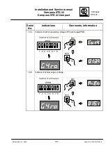
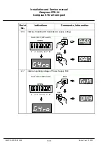
Page 129: ...tage 15VDC Nominal Value 14 5 15 5V 12 Step 7 Indicate inductive DC transmission supply voltage 60VDC Nominal value 58 0 62 0V 12 Step 8 Indicate internal operating voltage of Power Supply PCB 19VDC Nominal value 18 0 22 0V 12 Step 9 Indicate present current due to inductive transmission Nominal value 0 05 4 0A typical 2 0 A 12 Step 10 Indicate operating voltage of heating Nominal value 27 0 32 0V...

Page 130: ...inal value During start up 150 400mA During operation 120 350mA 12 Step 18 Indicate operating voltage 13 17VDC Nominal value 15 5V 12 Step 19 Indicate internal operating voltage 15VDC 14 5 15 5VDC 12 Step 20 Indicate internal operating voltage 24VDC 23 35 VDC 12 Step 21 Indicate pump voltage 24V 50Hz 24V 1V 50 Hz Nominal value 23 5 24 5V 12 Step 22 Indicate pump current 150mA Nominal value 140 180...

Page 131: ...ssor MC 1 on the outer sphere PCB 12 Step 27 Indicate program number and software version of the program for microprocessor MC 2 on the outer sphere PCB 12 Step 28 Operating time years 12 Step 29 Operating time hours 12 Step 30 Future purpose 12 Step 31 Future purpose 13 Error logbook SEC 1 to 35 DIP switch settings Speed Error Correction SEC for development purposes only see section 5 1 5 14 Dele...

Page 132: ...EA telegram setting 1 nN1 NMEA telegram repetition 1Hz choose set 2 nN10 NMEA telegram repetition 10Hz choose set 3 HE ro Heading telegram with ROT choose set 4 HE Heading telegram without ROT choose set 5 SECY Activate SEC choose set 6 SECn Deactivate SEC choose set 7 oELY SEC with oil residual error choose set 8 oELn SEC withot oil residual error choose set 9 ddUY System with DU choose set 10 dd...

Page 133: ...d log settings 1 PLoG Select for Puls log input choose set 2 PLd Select for Puls log input input interface inver ted choose set 3 PLd Select for Puls log input input inteface not inverted choose set 4 uhu Select for NMEA speed input choose set 5 ubu u Select for NMEA speed input speed though the water choose set 6 ubu G Select for NMEA speed input speed over ground choose set 7 GLoG select for GPS...

Page 134: ...g liquid temperature choose display 13 Li U Supporting liquid level choose display 14 Co73 73 V from ferrite transformer choose display 15 78 U 78 V stabilited for gyro AC converter choose display 16 GY U Gyro supply voltage choose display 17 GY A Gyro supply current choose display 18 Co15 15 V from ferrite transformer choose display 19 P 15 15 V stabilized choose display 20 P 24 24 V for pump AC ...

Page 135: ...splay 14 uhu Speed from NMEA telegram choose display 15 SPd L Speed data transfer choose display 16 PoS Latitude in degrees choose display 17 ASPd Speed alarms choose display 18 PoSn Latitude data transfer choose display 19 APoS Latitude alarm choose display 20 nAUC Number of telegrams with checksum choose display 21 nAn1 1st table of NMEA requests choose display 22 nAn2 2nd table of NMEA requests...

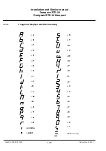
Page 136: ...nual Compass STD 22 Compass STD 22 Compact 126 Edition May 20 2005 3646 110 233 DOC010302 5 1 3 7 segment displays and their meaning A B C D E F T S U V W X Y Z 1 2 G H I J K L 3 4 M N O P Q R 5 6 7 8 9 0 comma point LF Line Feed ...

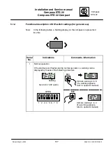
Page 137: ...lashing display on the compass is represented like this Serial No Indications Comments Information 1 Normal operation If the decimal point flashes during normal operation a warning can be displayed by means of the following procedure Switch B 37 DIP switch 1 2 3 4 5 6 7 8 OPEN flashing B38 B39 Indicate warning 1 to 4 if a warning appears refer to operator manual Indicate warning 4 to 8 if a warnin...

Page 138: ...ications Comments Information 2 Setting compass zero The compass zero must be set following installation Use the pier course from the sea chart as reference Switch B 37 DIP switch 1 2 3 4 5 6 7 8 OPEN B38 B39 B39 130 1 130 0 129 9 129 8 129 7 B38 B39 B38 1X 1X Setting compass zero Setting compass zero 130 5 130 4 130 3 130 2 130 1 ...

Page 139: ...egram per second 10 heading data transmission 10 telegrams per second HE ro heading with ROT HE heading only SECY heading data incorporating Speed Error Correction SECn heading data without Speed Error Correction oELY Speed Error Correction with oil residual error recommended setting oELn Speed Error Correction without oil residual error ddUY with connected Data Distribution Unit ddUn without Data...

Page 140: ...l Compass STD 22 Compass STD 22 Compact 130 Edition July 1 2005 3646 110 233 DOC010302 Serial No Comments Information Indications 3 cont Switch B 37 DIP switch 1 2 3 4 5 6 7 8 OPEN B38 B38 B39 B39 1 X 3X 4X 1X continued on next page ...

Page 141: ... 4 5 6 7 8 OPEN B38 B38 B39 B39 1 X 5X 6X 1X In some system configurations it is necessary to take off heading information from the compass direct additional to the heading information on the CAN bus This heading information is uncorrected without SEC Corrected heading information with SEC can be taken off in these system configurations from the distribution unit only On adjustment SECY continued ...

Page 142: ...22 Compact 132 Edition July 1 2005 3646 110 233 DOC010302 Serial No Comments Information Indications 3 cont Switch B 37 DIP switch 1 2 3 4 5 6 7 8 OPEN B38 B38 B39 B39 1 X 7X 8X 1X With Speed Error Correction has to be set always to oELY continued on next page ...

Page 143: ...ly 1 2005 3646 110 233 DOC010302 Serial No Comments Information Indications 3 cont Switch B 37 DIP switch 1 2 3 4 5 6 7 8 OPEN B38 B38 B39 B39 1 X 9X 10X 1X Has always be set to ddUY in case of STD 22 Gyro Compass Has always be set to ddUn in case of STD 22 Compact Gyro Compass continued on next page ...

Page 144: ...Installation and Service manual Compass STD 22 Compass STD 22 Compact 134 Edition July 1 2005 3646 110 233 DOC010302 Switch B37 DIP switch 1 2 3 4 5 6 7 8 OPEN B38 B38 B39 B39 1X 11X 12X 1X ...

Page 145: ...CAN bus users Every CAN bus user has an address This address may be assigned within the system only once The CAN bus address for compasses in general can be set within a range from 10 to 19 se table below The address 00 may not be used Switch B 37 DIP switch 1 2 3 4 5 6 7 8 OPEN B38 B39 each time pressed changes downwards each time pressed changes upwards Example Devices CAN bus address 1 Operator...

Page 146: ...233 DOC010302 Serial No Indications Comments Information 5 Set the interfaces for Channel 1 and Channel 2 For STD 22 Compact Compass only HSEr Heading serial Course bus nMEA NMEA 0183 The flashing setting is accepted Switch B 37 DIP switch 1 2 3 4 5 6 7 8 OPEN B38 B39 1X B39 2X B38 continued on next page ...

Page 147: ...and Service manual Compass STD 22 Compass STD 22 Compact 137 Edition Sept 13 2005 3646 110 233 DOC010302 Serial No Indications Comments Information cont No 5 Switch B 37 DIP switch 1 2 3 4 5 6 7 8 OPEN B38 3X B39 4X B39 5X B38 B38 ...

Page 148: ...his information is supplied together with the course data to connected course receivers Press button B38 to toggle between the two possible polarities Press button B39 to select the polarity of the rate of turn The indications in the flashing display are selected A positive rate of turn is indicated by the absence of a minus sign Switch B 37 DIP switch 1 2 3 4 5 6 7 8 OPEN P polarity B38 B39 2X 1X...

Page 149: ... Bridging over settling time CAUTION When the settling in stage is by passed the display and all connected course receivers indicate that the course data is usable even though there may be significant deviations FOR SERVICE PURPOSES ONLY Switch B 37 DIP switch 1 2 3 4 5 6 7 8 OPEN Example B38 1X B39 After the DIP switch is set into zero position the settling stage is by passed ...

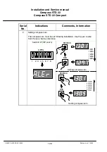
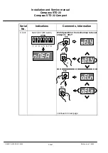
Page 150: ...interface inverted PLd Puls Log polarity of the input interface not inverted uhu NMEA Log means water speed in general ubu u means NMEA Log specified with speed through the water ubu G means NMEA Log specified with speed over ground GLoG GPS receiver speed The indications in the flashing display are selected If the setting does not correspond to the connected device the course correction relay res...

Page 151: ...2 Installation and Service manual Compass STD 22 Compass STD 22 Compact 141 Edition Sept 13 2005 3646 110 233 DOC010302 Serial No Comments Information Indications cont No 8 B38 5 X B39 3X B38 3X B39 1X B39 1X B38 4X ...

Page 152: ...Installation and Service manual Compass STD 22 Compass STD 22 Compact 142 Edition Sept 13 2005 3646 110 233 DOC010302 Serial No Comments Information Indications cont No 8 6X B39 1X B38 7X B39 1X B38 ...

Page 153: ...e connected to the Distribution Unit Switch B 37 DIP switch 1 2 3 4 5 6 7 8 OPEN B38 B 39 1X 130 1 129 9 129 8 129 7 129 6 Outer sphere turns cw 130 1 130 2 130 3 130 4 130 5 Outer sphere turns ccw 1X 10 Check the fan the display and the follow up DO NOT PERFORM DURING HEATING STAGE The current course is displayed on the connected course receivers Switch B 37 DIP switch 1 2 3 4 5 6 7 8 OPEN B39 1X...

Page 154: ...CE ONLY These switches turn off the follow up system of the compass in other words the display no longer follows the course Caution The displayed course and the course for all connected course receivers do not correspond to the ship s course Switch B 37 DIP switch 1 2 3 4 5 6 7 8 OPEN B38 1X Follow Up oFF Follow up system turned off B39 1x The displayed value is exclusively for development purpose...

Page 155: ...ion Sept 13 2005 3646 110 233 DOC010302 Serial No Comments Information Indications 12 Indicate Encoder heading Switch B 37 DIP switch 1 2 3 4 5 6 7 8 OPEN B38 1X B39 1X 12 1 Indicate Alignment Error Switch B 37 DIP switch 1 2 3 4 5 6 7 8 OPEN B38 2X B39 1X Indicating the current Alignment Error ...

Page 156: ...o Comments Information Indications 12 2 Indicate SEC Speed Error Correction value The heading indication already takes this value into account Switch B 37 DIP switch 1 2 3 4 5 6 7 8 OPEN B38 3X B39 1X 12 3 Indicate supply voltage DC P Power input operating voltage 24VDC Switch B 37 DIP switch 1 2 3 4 5 6 7 8 OPEN B38 4X B39 1X ...

Page 157: ...on Sept 13 2005 3646 110 233 DOC010302 Serial No Comments Information Indications 12 4 Indicate Internal operating voltage of Power Supply PCB Switch B 37 DIP switch 1 2 3 4 5 6 7 8 OPEN B38 5X B39 1X 12 5 Indicate Encoder supply voltage Switch B 37 DIP switch 1 2 3 4 5 6 7 8 OPEN B38 6X B39 1X ...

Page 158: ...005 3646 110 233 DOC010302 Serial No Comments Information Indications 12 6 Indicate Inductive DC transmission supply voltage Switch B 37 DIP switch 1 2 3 4 5 6 7 8 OPEN B38 7X B39 1X 12 7 Internal operating voltage of Power Supply PCB Switch B 37 DIP switch 1 2 3 4 5 6 7 8 OPEN B38 8X B39 1X ...

Page 159: ... 3646 110 233 DOC010302 Serial No Comments Information Indications 12 8 Indicate Operating current inductive transmission for development purposes only Switch B 37 DIP switch 1 2 3 4 5 6 7 8 OPEN B38 9X B39 1X 12 9 Indicate operating voltage of heating Switch B 37 DIP switch 1 2 3 4 5 6 7 8 OPEN B38 10X B39 1X ...

Page 160: ... 233 DOC010302 Serial No Comments Information Indications 12 10 Heating voltage at heating element Switch B 37 DIP switch 1 2 3 4 5 6 7 8 OPEN B38 11X B39 1X 12 11 Indicate temperature of the supporting liquid in C Nominal value 49 4 C to 51 1 C Switch B 37 DIP switch 1 2 3 4 5 6 7 8 OPEN B38 12X B39 1X ...

Page 161: ...233 DOC010302 Serial No Comments Information Indications 12 12 Indicate supporting liquid level Indication 2 2 liquid level OK Indication 0 liquid level not OK Switch B 37 DIP switch 1 2 3 4 5 6 7 8 OPEN B38 13X B39 1X Li Liquid 12 13 Indicate operating voltage Switch B 37 DIP switch 1 2 3 4 5 6 7 8 OPEN B38 14X B39 1X ...

Page 162: ...dition Sept 13 2005 3646 110 233 DOC010302 Serial No Comments Information Indications 12 14 Indicate DC operating voltage for 400Hz Switch B 37 DIP switch 1 2 3 4 5 6 7 8 OPEN B38 15X B39 1X 12 15 Indicate gyro supply Switch B 37 DIP switch 1 2 3 4 5 6 7 8 OPEN B38 16X B39 1X ...

Page 163: ...ct 153 Edition Sept 13 2005 3646 110 233 DOC010302 Serial No Comments Information Indications 12 16 Indicate gyro current in mA Switch B 37 DIP switch 1 2 3 4 5 6 7 8 OPEN B38 17X B39 1X 12 17 Indicate operating voltage 15VDC Switch B 37 DIP switch 1 2 3 4 5 6 7 8 OPEN B38 18X B39 1X ...

Page 164: ... 13 2005 3646 110 233 DOC010302 Serial No Comments Information Indications 12 18 Indicate internal operating voltage 15VDC Switch B 37 DIP switch 1 2 3 4 5 6 7 8 OPEN B38 19X B39 1X 12 19 Indicate internal operating voltage 24VDC Switch B 37 DIP switch 1 2 3 4 5 6 7 8 OPEN B38 20X B39 1X ...

Page 165: ...ompact 155 Edition Sept 13 2005 3646 110 233 DOC010302 Serial No Comments Information Indications 12 20 Indicate pump voltage 24V 50Hz Switch B 37 DIP switch 1 2 3 4 5 6 7 8 OPEN B38 21X B39 1X 12 21 Indicate pump current Switch B 37 DIP switch 1 2 3 4 5 6 7 8 OPEN B38 22X B39 1X ...

Page 166: ...coder voltage Balancing voltage indication approx 512 approx 5mV Switch B 37 DIP switch 1 2 3 4 5 6 7 8 OPEN B38 23X B39 1X Button B39 hold down display in degree Button B39 released again display in a coded value appr 182 per degree 12 23 Indicate program number and software version of the program for the microprocessor on the sensor PCB Switch B 37 DIP switch 1 2 3 4 5 6 7 8 OPEN B38 23X B39 1X ...

Page 167: ...rmation Indications 12 24 Indicate program number and software version of the program for the microprocessor on the sensor PCB Switch B 37 DIP switch 1 2 3 4 5 6 7 8 OPEN B38 24X B39 1X 12 25 Indicate program number and software version of the program for microprocessor MC 1 on the outer sphere PCB Switch B 37 DIP switch 1 2 3 4 5 6 7 8 OPEN B38 25X B39 1X ...

Page 168: ...10302 Serial No Comments Information Indications 12 26 Indicate program number and software version of the program for microprocessor MC 2 on the outer sphere PCB Switch B 37 DIP switch 1 2 3 4 5 6 7 8 OPEN B38 26X B39 1X 12 27 Operating hours meter years Switch B 37 DIP switch 1 2 3 4 5 6 7 8 OPEN B38 27X B39 1X ...

Page 169: ...tion Sept 13 2005 3646 110 233 DOC010302 Serial No Comments Information Indications 12 28 Operating hours meter hours Switch B 37 DIP switch 1 2 3 4 5 6 7 8 OPEN B38 28X B39 1X 12 29 12 30 In F7 In F8 Both functions are for future purpose Switch B 37 DIP switch 1 2 3 4 5 6 7 8 OPEN B38 29X 30X ...

Page 170: ...ons 13 Error logbook Indication of errors and warnings stating the frequency of occurrence Switch B 37 DIP switch 1 2 3 4 5 6 7 8 OPEN B38 1X B39 1X B38 2x E L 3 B38 3x E L 4 B38 4x E L 5 B38 5x E L 6 B38 6x E L 7 24 Number of errors warnings occurring To delete error logbook press button B39 for approximately 10 seconds the actual indicated line is deleted ...
Page 171: ...10302 Serial No Comments Information Indications 14 Delete Error logbook complete Delete hours meter complete hours and years Switch B 37 DIP switch 1 2 3 4 5 6 7 8 OPEN B38 1X B39 Delete Error log complete Hold until Error log is deleted complete B38 2X B39 Delete hour meter complete Hold unitil hour meter is deleted complete ...

Page 172: ...sor PCB faulty PCbS E L 08 Follow up system faulty PCbS E L 09 CAN1 and CAN2 operating voltage faulty PCbC E L 10 Supporting liquid error PCbG E L 11 System voltage B21 5 B21 8 on outer sphere PCB faulty PCbG E L 12 Operating voltage 24V faulty PCbG E L 13 Operating voltage 15V faulty PCbG E L 14 Heating operating voltage B21 1 B21 4 faulty PCbG E L 15 Operating voltage 72V faulty PCbG E L 16 Oper...

Page 173: ...ance Seq no Indications Comments Notes 1 UnCo Uncorrected Compass course without speed error correction value Switch B37 DIP switch 1 2 3 4 5 6 7 8 OPEN B38 Displays the uncorrected gyro course Identical with Seq no 6 2 FF FahrtFehler Speed error the value by which the compass course is to be corrected result from SEC displayed in degrees display value approx max 10 see also number 3 1 2 3 4 5 6 7...

Page 174: ...his speed is provided from the connected and selected Log see also number 5 Displayed in knots astern sped knots is also possible 1 2 3 4 5 6 7 8 OPEN Switch B37 DIP switch B38 B39 Connected Log not providing any speed data 2x 4 br 10 Latitude Breite at a resolution of 1 10 1 2 3 4 5 6 7 8 OPEN Switch B37 DIP switch B38 B39 No latitude data available GPS receiver defective 3x ...

Page 175: ...Comments Notes Indications 5 Corr Corrected course course taking SEC into account 1 2 3 4 5 6 7 8 OPEN Switch B37 DIP switch B38 4x B39 The automatic Speed Error Correction function is defective Speed or and position faulty 6 _roh Rough course course without SEC 1 2 3 4 5 6 7 8 OPEN Switch B37 DIP switch B39 B38 5x Identical with Seq no 1 ...

Page 176: ...ion error Indicated in degrees 1 2 3 4 5 6 7 8 OPEN Switch B37 DIP switch B39 6x B38 The automatic Speed Error Correction function is defective Speed or and position faulty 8 _FF Speed Error FahrtFehler without acceleration error Indicated in degrees 1 2 3 4 5 6 7 8 OPEN Switch B37 DIP switch B38 7x B39 The automatic Speed Error Correction function is defective Speed or and position faulty ...

Page 177: ...error components 1 2 3 4 5 6 7 8 OPEN Switch B37 DIP switch B39 8x B38 The automatic Speed Error Correction function is defective Speed or and position faulty 10 Sci Serial Interface Schnittstelle telegram traffic on serial interface 1 2 3 4 5 6 7 8 OPEN Switch B37 DIP switch B39 9x B38 Contents alternate Digit 2 NMEA interface Speed in Digit 1 GPS reciver interface Digit 0 Sum of all telegrams on...

Page 178: ...e 1 2 3 4 5 6 7 8 OPEN Switch B37 DIP switch B39 10x B38 Display options PULS Pulse Log vTg Speed over ground vhW Speed trough water vTg and vhW corresponds to NMEA 0183 12 PULS Speed value from Pulse Log Indicated in Kts Displays no if no Pulse Log selected or connected Displays 0000 if there is no input from selected source Display range 80 Kts to 80 Kts astern and ahead 1 2 3 4 5 6 7 8 OPEN Swi...

Page 179: ...omments Notes Indications 13 vtG S Speed from GPS receiver telegram speed over ground 1 2 3 4 5 6 7 8 OPEN Switch B37 DIP switch B39 12x B38 No or faulty data from GPS receiver vTg telegram 14 vtG h Course value from GPS receiver telegram 1 2 3 4 5 6 7 8 OPEN Switch B37 DIP switch B39 13x B38 No or faulty data from GPS receiver vTg telegram ...

Page 180: ... or faulty serial speed data vHw telegram 16 SPd L Speed in knots from Log The speed for which the source has been selected is displayed The display alternates between 099 0 accepting value and say 052 8 speed in knots If no value is accepted transferred the display stays at 099 0 1 2 3 4 5 6 7 8 OPEN Switch B37 DIP switch B38 15x B38 If the display changes value similar as shown there is a data t...

Page 181: ...7 DIP switch B39 16x B38 No latitude data available GPS receiver defective 18 ASPd Alarm speed 1 2 3 4 5 6 7 8 OPEN Switch B37 DIP switch B39 17x B38 3 2 1 0 Digit 3 Speed OK Display 1 Speed OK Display 0 Speed not OK Digit 2 Speed Alarm Display 1 Speed Alarm Display 0 No Speed Alarm Digit 1 Auto Speed OK Display 1 Auto Speed OK Display 0 Auto Speed not OK Digit 0 Auto Alarm Display 1 Auto Speed Al...

Page 182: ...ved from automatic latitude input Indicated in degrees 1 2 3 4 5 6 7 8 OPEN Switch B37 DIP switch B39 18x B38 If the display changes value similar as shown there is a data transfer on this interface No change constant 099 9 means there is no data transfer 20 APoS Alarm position input 1 2 3 4 5 6 7 8 OPEN Switch B37 DIP switch B39 19x B38 0001 no position alarm 1100 positon o k ...

Page 183: ... OPEN Switch B37 DIP switch B39 20x B38 1st digit number of decoder requests 2nd digit number of read in NMEA telegrams with correct check sum 22 nAn1 1st table for NMEA requests 1 2 3 4 5 6 7 8 OPEN Switch B37 DIP switch B39 21x B38 L telegram type GLL G telegram type GGA t telegram type VTG h telegram type VHW 1st digit number of L types 2nd digit number of G types 3rd digit number of t types 4t...

Page 184: ...ch B37 DIP switch B39 22x B38 1x B38 1x b telegram type VBW l telegram type SLL 1st digit number of b types 2nd digit number of l types 24 nSGG NMEA telegram Strings of the GGA telegram 1 2 3 4 5 6 7 8 OPEN Switch B37 DIP switch B39 23x B38 The number of operations depends on the number of characters 1 display content max 4 ASCII character See sequ no 25 Number of ASCII char acters per telegram 00...

Page 185: ...mpact 175 Edition July 1 2005 3646 110 233 DOC010302 Seq no Comments Notes Indications 25 nSGL NMEA telegram Strings of the GLL telegram 1 2 3 4 5 6 7 8 OPEN Switch B37 DIP switch B39 24x B38 1x B38 2x B38 3x B38 4x B38 5x B38 6x Example Length of the telegram 44 ASCII characters ...

Page 186: ... STD 22 Compact 176 Edition July 1 2005 3646 110 233 DOC010302 Seq no Comments Notes Indications cont 25 nSGL NMEA telegram Strings of the GLL telegram 1 2 3 4 5 6 7 8 OPEN Switch B37 DIP switch B39 24x B38 7x B38 8x B38 9x B38 10x B38 11x B38 12x Checksum ...

Page 187: ... of the contact switch B38 the number of ASCII characters is displayed If the display shows 0000 no telegram output took place With every further operation of contact switch B38 4 consecutive ASCII characters are displayed 26 nSLL NMEA telegram Strings of the SLL telegram 1 2 3 4 5 6 7 8 OPEN Switch B37 DIP switch B39 25x B38 Number of ASCII char acters per telegram 0000 no telegram The number of ...

Page 188: ...1x Number of ASCII char acters per telegram 0000 no telegram The number of operations depends on the number of characters 1 display content max 4 ASCII characters See seq no 25 28 nStG NMEA telegram Strings of the VTG telegram 1 2 3 4 5 6 7 8 OPEN Switch B37 DIP switch B39 27x B38 1x The number of operations depends on the number of characters 1 display content max 4 ASCII characters See seq no 25...

Page 189: ... of the VBW telegram 1 2 3 4 5 6 7 8 OPEN Switch B37 DIP switch B39 28x B38 1x The number of operations depends on the number of characters 1 display content max 4 ASCII characters See seq no 25 Number of ASCII char acters per telegram 0000 no telegram 30 Development only Fb10 Software component of speed error correction Latitude 1 2 3 4 5 6 7 8 OPEN Switch B37 DIP switch B39 29x B38 Latitude ...

Page 190: ...FS10 Software component speed error correction Ship s speed 1 2 3 4 5 6 7 8 OPEN Switch B37 DIP switch B39 30x B38 Ship s speed kn 32 Development only FnSP Software component speed error correction North component of the ship s speed vector 1 2 3 4 5 6 7 8 OPEN Switch B37 DIP switch B39 31x B38 North component of the ship s speed vector with negative sign south component ...

Page 191: ...lopment only FutG Software component speed error correction Course over ground Value of the VTG telegram 1 2 3 4 5 6 7 8 OPEN Switch B37 DIP switch B39 32x B38 0000 no telegram 123 4 course value 34 tIME Time since activating speed error correction Reset with power off 1 2 3 4 5 6 7 8 OPEN Switch B37 DIP switch B39 33x B38 1x B38 2x B38 3x hours days max 99 minutes seconds ...

Page 192: ...5 Development only SCI Serial Communication Interface NMEA Log GPS input 1 2 3 4 5 6 7 8 OPEN Switch B37 DIP switch B39 34x B38 The content of the two digits is during a data transfer unrecognisable Just the digits 1 16 and 0 16 are visible for a short moment 10 16 means line feed All other sequentially indicated values are for development purpose only ...

Page 193: ...led water must not be changed whilst at sea except in the case of dual systems Tools special tools required Filling device Injector Spare parts required Supporting liquid Distilled water If required Screw distilled water Screw supporting liquid Screw ventilation 6 1 1 Removing the outer sphere from the compass enclosure Wait min 15 minutes until the gyrosphere does not turn any more Turn off the 2...

Page 194: ...e 66 1 under 2 of the 4 snap closures and release them by pressing with the thumbs Carefully turn the outer sphere through 90 and repeat the process with the other two snap closures The outer sphere is now free and can be removed Still holding the outer sphere with both hands lower it slightly this releases the locking device carefully remove it from the compass enclosure and set it down ...

Page 195: ... 67 Remove the ventilation screw Figure 67 1 to vent the system Remove the supporting liquid screw Figure 67 2 so that the supporting liquid can be poured out Holding the outer sphere with both hands pour out the supporting liquid and throw it away no special measures are needed for disposal Remove the distilled water screw Figure 67 3 so that the distilled water can be poured out Remove the remai...

Page 196: ...the distilled water container has flowed into the outer sphere and then carefully repeat the pouring out process If necessary use the injector to suck out the remaining distilled water through the distilled water filling opening Attach the filling device to the distilled water bottle and pour the entire contents 230cm3 into the distilled water filling opening look for the identifying label Close t...

Page 197: ...p closures on the pendulum joint Using the thumbs press down and engage the two snap closures Carefully turn the outer sphere through 90 and repeat the process with the other two snap closures The outer sphere is now fastened to the pendulum joint Guide the cable with the plug to the left around the outer sphere and plug it in as shown in Figure 66 2 Close the door of the enclosure and fasten it w...

Page 198: ...2 Compact 188 Edition Feb 17 2006 3646 110 233 DOC010302 7 Error messages and warnings 7 1 Error messages An error is indicated in the digital display of the compass by a flashing Erro for error HEADING IS NOT DISPLAYED Figure 69 Error message in digital display ...

Page 199: ...ty PCbS E L 07 CAN dialogue from outer sphere PCB to sensor PCB faulty PCbS E L 08 Follow up system faulty PCbS E L 09 CAN1 and CAN2 operating voltage faulty PCbC E L 10 Supporting liquid error PCbG E L 11 System voltage B21 5 B21 8 on sensor PCB faulty PCbG E L 12 Operating voltage 24V faulty PCbG E L 13 Operating voltage 15V faulty PCbG E L 14 Heating operating voltage B21 1 B21 4 faulty PCbG E ...

Page 200: ...20 2005 3646 110 233 DOC010302 7 2 Warnings Warning indicate a malfunction during operational use The heading continues to be displayed A warning is indicated by a flashing decimal point B39 B38 Warning 4 Examples of warning flashing Warning 1 Figure 70 DIP switch B37 and button B38 B39 ...

Page 201: ... it therefore follows that the fan is defective if this warning is displayed To prevent overheating due to fan failure it is recommended that you do the following Check whether the fan screen is covered and check to see that air can enter the enclosure unhindered at the base Open the door on the compass If necessary cool the outer sphere using an external fan These measures should be continued unt...

Page 202: ...Close the door on the compass or introduce warm air These measures should be continued until warning 2 stops It is essential that the heater be repaired at the earliest opportunity 7 2 3 Warning 3 Supporting liquid 60 C This warning is output when the temperature of the supporting liquid is higher than 60 C To prevent the temperature from rising further it is recommended that you do the following ...

Page 203: ...nly you must establish the cause possibly a leak and correct the fault If the level of supporting liquid is too low the gyro current is interrupted and an Error is displayed the heading information will not longer displayed as well as the heading information to the connected heading receivers Please note At the Operator Unit for Gyro compass STD 20 this warning is shown as C4 Temperature 7 2 5 War...

Page 204: ...ation ID 0000 1023 Age of Differential GPS data Geoidal separation meters Altitude re mean sea level geoid meters Horizontal dilution of precision Number of satellites in use 00 12 may be different from the number in view GPS Quality indicator Longitude E W Latitude N S UTC of position NMEA 0183 Format GLL GLL Geopgrphic Position Latitude Longitude GLL llll ll a yyyyy yy a hhmmss ss A a hh CR LF M...

Page 205: ...e of Turn degrees minute bow turns to port Staus A Data valid NMEA 0183 Format HDT HDT Heading True HDT x x T hh CR LF reading degrees True NMEA 0183 Format HDG HDG Heading Magnetic HDG x x hh CR LF Magnetic sensor heading degrees NMEA 0183 Format VTG VTG Velocity Through Ground Talker VTG x x T x x M x x N x x K hh CR LF Speed km hr Speed knots Heading degrees Magnetic Heading degrees True ...

Page 206: ... STD 22 Compass STD 22 Compact 196 Edition May 20 2005 3646 110 233 DOC010302 NMEA 0183 Format VHW VHW Water Speed and Heading Talker VHW x x T x x M x x N x x K hh CR LF Speed km hr Speed knots Heading degrees Magnetic Heading degrees True ...

Page 207: ...Compass STD 22 Installation and Service manual Compass STD 22 Compass STD 22 Compact 197 Edition May 20 2005 3646 110 233 DOC010302 intentionally left blank ...

Page 208: ...Kompaß STD 22 Installation and Service manual Compass STD 22 Compass STD 22 Compact 1 Edition May 20 2005 3646 110 233 DOC010302 ...

Page 209: ...Installation and Service manual Compass STD 22 Compass STD 22 Compact 2 Edition May 20 2005 3646 110 233 DOC010302 ...

Page 210: ...Kompaß STD 22 Installation and Service manual Compass STD 22 Compass STD 22 Compact 3 Edition July 1 2005 3646 110 233 DOC010302 ...

Page 211: ...Installation and Service manual Compass STD 22 Compass STD 22 Compact 4 Edition May 20 2005 3646 110 233 DOC010302 intentionally left blank ...

Page 212: ...o Compass STD 22 Type 110 233 NG001E10 ANSCHÜTZ Ersatzteilkatalog SPARE PARTS CATALOGUE 1 14 628 Kompaß STD 22 Installation and Service manual Compass STD 22 Compass STD 22 Compact 5 Edition Sept 13 2005 3646 110 233 DOC010302 ...

Page 213: ...ompaß STD 22 Gyro Compass STD 22 Type 110 233 NG001E10 ANSCHÜTZ Ersatzteilkatalog SPARE PARTS CATALOGUE Installation and Service manual Compass STD 22 Compass STD 22 Compact 6 Edition Sept 13 2005 3646 110 233 DOC010302 ...

Page 214: ... 13 3604661 Klemmleiste mit Temperatursensor Terminal PCB with Temperature Sensor 110 233 X09 1 D2865 14 3602315 Pumpe Pump 110 231 40 1 D2865 15 3602608 Heizung kompl Heater compl 110 231 X01 1 D2865 16 3604568 Hüllkugel kompl Outer Sphere compl 110 233 X04 1 D2865 17 3604571 Untere Hüllkugel Lower Hemisphere 110 233 X02 1 D2865 18 1502254 Tragflüssigkeit Supporting Liquid 148 162 E01 1 D2865 681...

Page 215: ...Installation and Service manual Compass STD 22 Compass STD 22 Compact 8 Edition Sept 13 2005 3646 110 233 DOC010302 intentionally left blank ...

Page 216: ...E2 Channel1 1A T 11 Plug B3 serial Interface NMEA Coursebus Channe2 12 Fuse E3 Channel2 1A T 13 LED H5 Function indicator of relay D4 AVAILABLE 14 Plug B4 Output Coursebus 15 Fuse E4 Coursebus output 1A T 16 Plug B6 Statussignals 17 LED H7 Output Channel2 lights up red Coursebus 18 LED H11 Output Channel2 lights up green NMEA 19 LED H10 Output Channel1 lights up green NMEA 20 LED H6 Output Channel...

Page 217: ...1 Processor Reset 5 LED H1 Processor monitoring 6 Plug B3 Connection to the step motor 7 Jumper B4 Testpurpose only Output Coursebus or NMEA 8 Plug B9 Connection for programming FLASH PROM 9 DIP switch B37 Setting of parametrs and operation modes read out of Compass information 10 Push button B39 Selection and setting in combination with DIP switch 11 Display Selection and setting in combination w...

Page 218: ...tion for Ship s supply 24VDC 5 Plug B5 Connection inductivity secondary coil 6 LED H3 Operating voltage relay supply 12VDC 7 Ülug B50 Connection to the Sensor PCB 8 Jumper B7 Only for manufacturers application 9 LED H9 Operating voltage Shaft Encoder 15VDC 10 Plug B2 Connection for programming FLASH PROM 11 LED H6 lights up red while programming 12 Jumper B3 Must be set to FLASH the processor 13 P...

Page 219: ...ernal CAN bus 5 Plug B23 Connection to the terminal Strip PCB 6 LED H1 Processor clock MC1 7 Push button B11 Reset function after flashig of MC1 8 LED H3 Flashing MC1 lights up when jumper B20 is insterted 9 Jumper B20 Has to be inserted to flash MC1 10 Plug B18 Connection to flash MC1 11 LED H2 Flashing MC2 lights up when jumper B 19 is inserted 12 Plug B8 Connection to flash MC2 13 Jumper B19 Ha...

Page 220: ...oltage 5V DC 11 LED H10 Output Channel1 lights up green NMEA 12 Fuse E2 Channel1 1A T 13 Plug B3 serial Interface NMEA Coursebus Channel2 14 LED H7 Output Channel2 lights up red Coursebus 15 LED H11 Output Channel2 lights up green NMEA 16 Fuse E3 Channel2 1A T 17 Plug B4 Output Coursebus 18 LED H12 Output Coursebus B4 lights up red Coursebus 19 LED H5 Function indicator of relay D4 AVAILABLE 20 Fu...

Page 221: ... NMEA THREESTATE MODUL 6 Plug B3 Connection to the step motor 7 Plug B9 Plug to connect external devices in the Service Mode 8 LED H2 Blinking while Service Mode 9 Switch B6 Switschin on into Service Mode 10 Push button B39 Selection and setting in combination with DIP switch 11 DIP switch B37 Selection and setting in combination with DIP switch 12 Display 13 Push button B38 Selection and setting ...

Page 222: ...24VDC 5 Plug B5 Connection inductivity secondary coil 6 LED H3 Operating voltage relay supply 12VDC 7 Ülug B50 Connection to the Sensor PCB 8 Jumper B7 Only for manufacturers application 9 LED H9 Operating voltage Shaft Encoder 15VDC 10 Plug B2 Connection for programming FLASH PROM 11 LED H6 lights up red while programming 12 Jumper B3 Must be set to FLASH the processor 13 Push button B10 Prozesso...

Page 223: ...y 4 Plug B30 Internal CAN bus 5 Stecker B23 Connection to the terminal Strip PCB 6 LED H1 Processor clock MC1 7 Push button B11 Reset function after flashig of MC1 8 Plug B18 Connection to flash MC1 9 LED H3 Flashing MC1 light up when Plug B18 is connected 10 LED H2 Flashing MC2 lights up when Plug B8 is connected 11 Plug B8 Connection to flash MC2 12 Push button B10 Reset function after flashing ...

Page 224: ......

Page 225: ......

Page 226: ......

Page 227: ......

Page 228: ......

Page 229: ......

Page 230: ......

Page 231: ......

Page 232: ......

Page 233: ......

Page 234: ......

Page 235: ......

Page 236: ......

Page 237: ......

Reviews:

Related manuals for 110-233