Magnetic Sonde
7 Installation and Maintenance
Edition:003
17
4423
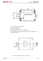
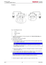
Fig. 6: Drilling Scheme, Junction Box
/3).
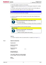
4. Install the junction box (
/1) with 2 suitable screws.
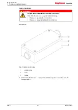
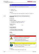
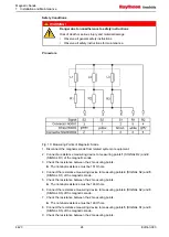
5. Connect the cable of the responding system or equipment to the terminal strip, see
attached wiring diagram.
Fig. 7: Terminal Assignments of Junction Box CP 500JB
Summary of Contents for 108-010.NG001 E01
Page 6: ...Magnetic Sonde List of Figures 4423 IV Edition 003 ...
Page 8: ...Magnetic Sonde List of Tables 4423 VI Edition 003 ...
Page 10: ...Magnetic Sonde List of Abbreviations 4423 VIII Edition 003 ...
Page 55: ...12 02 10 ...
Page 56: ...07 10 11 Lut 23 11 11 ...
Page 57: ...07 10 11 Lut 23 11 11 ...
Page 58: ...12 01 10 ...
Page 62: ...Magnetic Sonde Illustrated Spare Parts Catalog 4 4 Edition 001 Intentionally left blank ...
Page 73: ...Magnetic Sonde Illustrated Spare Parts Catalog Edition 001 15 4423 Intentionally left blank ...
Page 80: ...Magnetic Sonde Illustrated Spare Parts Catalog 4423 22 Edition 001 Intentionally left blank ...


