


29
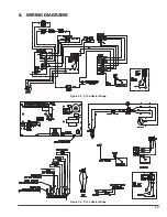
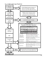
Power On
Is the water
temperature displayed?
NO
YES
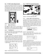
Push
MODE
switch to select
"
Pool
" or "
Spa
"
Push Temp
arrow to scroll to
desired temperature
NO
Water temperature
and set
temperature
displayed?
YES
“
Heating
” will
display briefly
NO
NO
YES
YES
Flame icon displayed
and flashing?
OR
Water temp displayed?
(pilot lit and rectified)
Heater Fired?
END
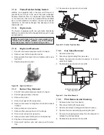
• Check On/Off switch (under lid on control panel)
• Check for 120/240 volts to the transformer
(time clock, circuit breaker, wire connections)
• Check for 24 volts to Circuit Board (P6 connector)
“
Remote
” and Water Temperature displayed
(a remote control is controlling the heater)
Note: Disconnect the remote by turning the
remote function off. See page 36 for instructions.
NO
YES
Is a fault code displayed and flashing?
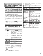
Diagnostic Readouts
“
Sensor Failure
,” “
Sensor Open
” or “
Sensor Short
” -
Temperature sensor out of range (replace sensor)
Verify power at MV on P-4 Terminal on digital circuit board.
Verify power to valve MV voltage. (Replace valve.)
“
Spark
”
Temp Degrees F 40 50 60 70 80 90 100 106
Temp Degrees C 4.4 10 15.6 21.1 26.7 32.2 37.8 41.1
Resistance (k) 261.1 199.0 153.1 118.8 93.0 73.3 58.3 51.0
If okay, replace Circuit Board
Sensor Failure
Inspect thermister, wires, and connector at Terminal P1
Check resistance value of the thermister. Reference to chart below.
Replace thermister if not within 10% of values shown below.
If okay, replace Circuit Board.
Sensor resistance at various temperatures
“
Water Sw Open
”
Pressure switch. Verify water flow and pressure
CLEAN FILTER / STRAINER - backwash if neccessary.
“
Hi Limit 1 Fault
”
High limit switch. Verify water flow. Inspect internal
“
Hi Limit 2 Fault
”
Thermostat (Unitherm Governor) and bypass valve.
“
Rollout Sw Open
”
Rollout Sensor - Check for blocked heat exchanger and soot.
Atmospheric Units - Replace fusible link.
Lo NOx Units - Press manual reset button.
“
Clock/Fireman Sw
”
Fireman or Remote switch connected to safety loop is in the
OFF mode.
“
Vent/Field Sw #1
”
Vent switch open. Check connections to the board.
If extractor installed, troubleshoot extractor.
“
Ignition Lockout
”
Ignition lockout. Check power at pilot valve. Check spark (bad
ignition circuit or hi-tension wire). Verify clean pilot orifice and
clearance from igniter to ground hood.
“
Ignition Failure
”
Ignition failure. Verify gas to the heater. Verify valve operation
(gas present at tube fitting).
8.3. P-156 Control Logic Flow Chart
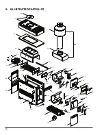
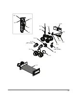
Summary of Contents for 106
Page 23: ...23 6 WIRING DIAGRAMS Figure 35 P 106 Heater Wiring Figure 36 P 156 Heater Wiring...
Page 34: ...34 NOTES...
Page 35: ...35 NOTES...


