


Chapter 5: Installation
59
The instrument can be installed either above or below deck, provided
the rear of the instrument is sited where it is protected from contact
with water.
The instrument must also be positioned where it is:
• Within easy reach of the steering position.
• Protected from physical damage.
• At least 230 mm from any compass.
• At least 500 mm from any radio/radar receiving/transmitting
equipment.
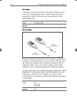
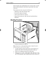
Mounting Procedure
2
3
1
1 Cable boss 2 Fixing studs 3 Thumb nuts
Note:
Always leave a 6 mm gap between adjacent display heads to
allow the protective sun covers to be fitted.
1.
Use the template provided (after the
Index
in this handbook) to
mark the hole centres for the fixing stud and the cable boss.
2.
Drill four 5 mm diameter holes for the fixing studs.
3.
Taking great care not to cut the hole for the cable boss too big,
use a 90 mm diameter cutter to drill the hole for the cable boss (1).
118ch05.p65
07/01/99, 12:43
59
Summary of Contents for ST7000
Page 2: ...ST7000 Plus Autopilot Control Unit Owner s Handbook Document number 81118_1 Date 20January1999...
Page 3: ......
Page 5: ...ii ST7000PlusAutopilotControlUnitOwner sHandbook...
Page 13: ...x ST7000PlusAutopilotControlUnitOwner sHandbook...
Page 17: ...xiv ST7000PlusAutopilotControlUnitOwner sHandbook...
Page 51: ...34 ST7000PlusAutopilotControlUnitOwner sHandbook...
Page 53: ...36 ST7000PlusAutopilotControlUnitOwner sHandbook...
Page 83: ...66 ST7000PlusAutopilotControlUnitOwner sHandbook...
Page 95: ...78 ST7000PlusAutopilotControlUnitOwner sHandbook...
Page 105: ......