background image

21                                                                                                                                                  Raymarine Sirius Weather System  Installation Guide

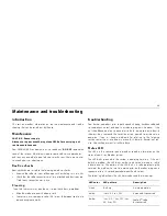
It is normal during the first minute of initial power that the receiver status

LED shows no activity and remains off. During the second minute the status

LED will start to flash the amber or red fault strings. Typically, during

normal operation, a flashing green LED will occur within 90 seconds of

initial power. If there is no LED indication of any sort displayed after 90

seconds you should check the inline fuse or circuit breaker.

A blinking 

Red

 LED indicates an internal fault condition. If this condition

persists contact Raymarine Technical Services.

Accessories

The following accessories are available from your local dealer, national 
distributor or Raymarine Customer Service Department:

The following accessories are available from your local Shakespeare dealer:

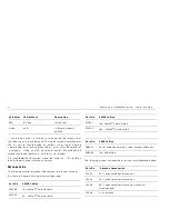
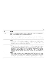
Red

Blinking

Internal fault

Amber

Solid

1st Minute of power 

up(SR50)


Part No.

 SR100 Cables

E55049

1.5 m SeaTalk

hs

 Network cable 

E55050

5 m    SeaTalk

hs

 Network cable


LED color

LED pattern

Description

E55051

10 m SeaTalk

hs

 Network cable

E55052

20 m   SeaTalk

hs

 Network cable

Part No.

 SR50 Cables

R69053

3 m for SeaTalk

NG

 Network Ycable (Network and Power)

R08265

1.5m Audio cable


Part No

 Antenna Accessories

SRS35

35 ft. antenna cable and connectors

SRS50

50 ft. antenna cable and connectors

SRS90

90 ft. antenna cable and connectors (Maximum 

recommended).

SRA40

Sirius Antenna


Part No.

 SR100 Cables

Summary of Contents for SR100

Page 1: ...SR50 SR100 Sirius Weather Systems Installation Guide Document Number 87069_1 Date December 2006...

Page 2: ...eting territories AST Autoadapt Auto GST Autoseastate Autotrim Bidata Marine Intelli gence Maxiview On Board Raychart Raynav Raypilot Raystar ST40 ST60 Seaclutter Smart Route Tridata and Waypoint Navi...

Page 3: ...System connections 14 System activation 18 Upgrading weather receiver software 19 Maintenance and troubleshooting 20 Introduction 20 Maintenance 20 Troubleshooting 20 Accessories 21 Glossary of weath...

Page 4: ...ce By using this service you acknowledge and agree that you have read the terms of the subscription agreement for this service and agree to all of the terms contained therein If you do not have the su...

Page 5: ...acies or omissions it may contain In addition our policy of continuous product improvement may change specifications without notice As a result Raymarine cannot accept liability for any differences be...

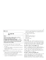
Page 6: ...hey develop WARNING Product installation This equipment must be installed and operated in accor dance with the Raymarine instructions provided within this guide Failure to do so could result in poor p...

Page 7: ...ive ground boats The power cable earth screen must be connected to the boat s RF ground system CAUTION Software upgrade While this software upgrade is not intended to erase data stored in your display...

Page 8: ...e distance should be increased to 7 ft 2 m More than 7 ft 2 m from the path of a radar beam A radar beam can normally be assumed to spread 20 degrees above and below the radiating element The product...

Page 9: ...10 ft 3 m Power cable 25 ft 7 6 m Antenna cable 10 ft 3 m Power cable SeaTalkNG network Y cable Audio cable D9061 1 M8 screw x4 M3 5 screw x3 SRA 40 Antenna Mounting gasket Weather receiver module Su...

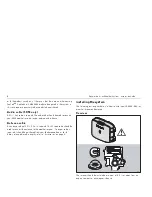
Page 10: ...d dangers and other obstruction MIN MAX 10 55 14 130 D9063 1 Protect the receiver from extremes of temperature DO NOT place the receiver near an engine or where fuel vapor could be present DO NOT inst...

Page 11: ...ing to your boats power supply This cable may be extended to a distance of 60 ft 20m using a suitable wire gauge AWG 12 or greater For full details of power connections refer to Power cable on page 15...

Page 12: ...r to your external audio device Antenna cable An antenna cable of 25 ft 7 5m is supplied This RF coax cable should be used to connect the antenna to the weather receiver If a longer cable is required...

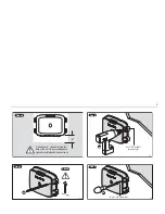
Page 13: ...mum 6 space must be left below the unit to ensure adequate space for cable bends connections Step 1 Check x4 Vertical D9066 1 Use 7 64 drill bit for pilot holes Step 2 x4 D9067 1 No 8 x 3 4 screw x4 S...

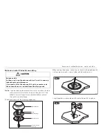
Page 14: ...nents When selecting the antenna installation site check that the area below the site has easy access and is clear of cables and other obstructions Using the gasket as a template mark the center hole...

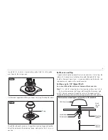
Page 15: ...9 16 hole drilled in the mounting surface It is recommended to seal the hole drilled to prevent water ingress with a suitable sealant Surfaces up to 1 4 6mm thick Do not cut the cable and do not remov...

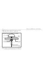
Page 16: ...1 4 6mm to 1 25 4mm thick Note A standard 1 x 14TPI generic rail mount is also available Refer to individual manufacturers installation guides for fitting instructions SRA 40 antenna Extension shaft 6...

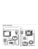
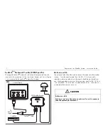
Page 17: ...e shown in the following illustrations SR50 SR100 C Series Display Antenna Weather Receiver Amplifier SR50 D9939 1 Power Supply RANGE CANCEL OK PAGE ACTIVE WPTS MOB MENU DATA IN OUT Power Supply CANCE...

Page 18: ...e connector panel also contains a light emitting diode LED to indicate system status for diagnostic purposes For full details of the status LED refer to Status LED on page 20 Power cable Sirius weathe...

Page 19: ...er system by connecting the Shield wire screen of the power cable to the nearest ground point on your boat s RF system If you need to extend the wire the extension wire should be an 8 mm braid or AWG...

Page 20: ...ver If a cable length greater than the 25 ft 7 5 m supplied is required a substitute cable of suitable length should be purchased from your Shakespeare dealer ensuring that a maximum length of 90 ft 2...

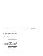
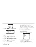
Page 21: ...elevant display handbook 2 Press the MENU key The Setup dialog box appears 3 Use the trackpad to highlight Weather Setup Menu 4 Use the trackpad to enter Weather Setup Menu Your Sirius Weather ID numb...

Page 22: ...flashing amber 2 Insert a CF card containing the software upgrade into the display Power up your display you will see the Upgrade Utility screen Ensure the software upgrade version is highlighted in...

Page 23: ...ooting Your Raymarine product prior to packing and shipping has been subjected to comprehensive test and quality assurance programs However if the unit should develop a fault please refer to the follo...

Page 24: ...ces Accessories The following accessories are available from your local dealer national distributor or Raymarine Customer Service Department The following accessories are available from your local Sha...

Page 25: ...sting service please quote the following product information Equipment type Model number Serial number Product Repair and Service Raymarine Product Repair Center 21 Manchester Street Merrimack NH 0305...

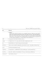
Page 26: ...low pressure Alsocalleda cyclone Dry line Aregionwherethereisastronggradientindewpointtemperatures Itisoftenfoundinaregionwherestrongthunderstormsdevelop Forecast Somethingthattellsuswhatthe weatheris...

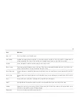
Page 27: ...structural damage to small residences and utility buildingswith a minoramount of curtainwall failures Damage toshrubbery andtreeswith foliage blown off treesandlarge trees blowndown Mobile homesand po...

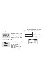
Page 28: ...eevacuation of residential areason low ground within 5 10 miles 8 16 km of the shoreline may be required Isobar A line on a weathermap linking areas with equal airpressure Lightning Discharge of stati...

Page 29: ...the earth s surface Tropical depression Anorganizedsystemofcloudsandthunderstormswithadefinedsurfacecirculationandmaximumsustainedwindsof38mph 33kt orless Tropical storm Anorganizedsystemof strongthun...

Page 30: ...installed and connected in accordance with the instructions contained in the Installation and Connection sections of this handbook Your C or E Series display is running a version of software that inc...

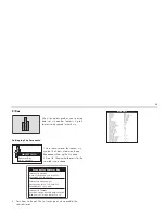
Page 31: ...oft keys appear 2 Toggle the Watchbox softkey to ON or OFF as required 3 Toggle the Marine Zones soft key to HIDE or SHOW as required 4 Press OK to accept your choice and return to the top level soft...

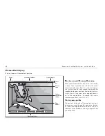
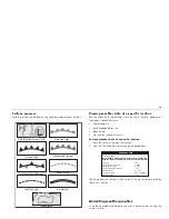
Page 32: ...will be lost if you zoom out a long way Zoom in until all the required detail is displayed To re center the map on your boat press FIND SHIP Placing waypoints The waypoint button and softkeys operate...

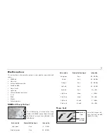
Page 33: ...type and level of precipitation a defined in the table below Storm Cast Storm Cast arrows indi cate the direction and speed of a storm Color code Precipitation type Intensity Light green Rain 15 19 d...

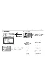
Page 34: ...n radar shows the precipitation levels for Canada but unlike NOWRad it does not show the precipitation type 26 Storm OK for more info OBJECT INFO Storm cast VXNO 5 760NM 057 o T 1 6kl 08 40AM 24 o 44...

Page 35: ...Tropical storm data You can display tropical storm data for a selected storm This data includes Storm s name and type Date and time Position direction and speed Pressure and maximum wind speed and gus...

Page 36: ...stations are represented according to type by a pink symbol as follows Diamond Buoy station Triangle Coastal Marine Automated Network C MAN Circle Weather Service International WSI Square National Wea...

Page 37: ...dy skies Low near 20F Winds NW at 5 to 10 mph Forecast for Tuesday Sunshine along with some passing clouds High near 25F Winds NW at 5 to 10 Forecast for Summer Bay Station ID Station Name Station Typ...

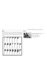
Page 38: ...nd speed Wind barbs give a more precise indication of wind speed as shown on the illustration below Waves The waves option shows current wave height in up to 16 shades of color Reds Highest waves Gree...

Page 39: ...he dialog box also contains a description of the marine zone selected by the cursor s position Animatingweathergraphics Using the animated weather option you can view an animation from the current tim...

Page 40: ...er of these controls will restart the animation The animation will stop if any of the function buttons is pressed e g ACTIVE Viewing weather reports The weather application can display the following r...

Page 41: ...s and thunderstorms You can display a report of all current watchbox warnings These warnings show that a weather warning is in place for a specific area This area is defined by the warning itself In a...

Page 42: ...fined by the alert To show watchbox data 1 Place the cursor over the relevant polygon The Object Information dialog box appears 2 Press View Warning soft key THe Watchbox warning appears Watchbox stat...

Page 43: ...our local dealer national distributor or Raymarine Technical Services Department for further advice If weather data is not being received check Status bar signal strength Soft key operation and applic...

Page 44: ...C non condensing Receiver Size 10 x 7 x 2 273 3 x 187 2 x 61 7 mm Weight 2 2 lbs 1 kg Mounting Four keyholed mounting tabs screws Power Voltage Current Fuse Reverse polarity protected 9 V to 32 V DC...

Page 45: ...2 273 3 x 187 2 x 61 7 mm Weight 2 2 lbs 1 kg Mounting Four keyholed mounting tabs screws Power Voltage Current Fuse Reverse polarity protected 9 V to 32 V DC 0 7 A at 9 V 2 A peak 2A recommended Conn...

Page 46: ...nt EMC Electromagnetic Compatibility FCC Federal Communications Commission ft feet IMO International Maritime Organization LED Light Emitting Diode m meters mm millimeters NWS National Weather Service...

Page 47: ...44...

Page 48: ...45 Raymarine Sirius Weather System Installation Guide...

Reviews: