


2-6
Raystar 120 GPS Receiver
connector block, referring to Table 2-1 and the diagrams shown in
Figure 2-3 to Figure 2-3 below.
Note: As with all onboard marine equipment, the installer should en-
sure that the power supply connection to the Raystar 120 is adequate-
ly protected by a suitably rated fuse or circuit breaker. This will be
provided, typically, by connection via a fused display unit.
Note:
-
Unused wires must be insulated and taped back.
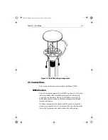
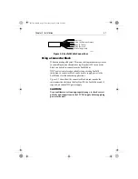
Connection is made via a 33ft (10m) cable terminated with a moulded
6-pin connector as detailed in Figure 2-3 .
Figure 2-3: NMEA Connector Pin-outs
SeaTalk Version
Connection is made via the 10m (33ft) cable with bare ends suitable
for connection to an existing SeaTalk bus as detailed in Figure 2-4 .
Table 2-1: Raystar 120 NMEA Interconnections
Pin No
Colour
Function
1
Red
Power
2
3
Screen
0V / Ground
4
Yellow
NMEA Out
5
Green
NMEA In
6
Brown
RTCM in
3
Screen (0V/ground)
2
Screen
(0V/ground)
1
Red
(Power )
4
Yellow
(NMEA out)
5
Green
(NMEA in)
6
Brown (RTCM in)
D4727-1
81170_2.BOOK Page 6 Thursday, July 19, 2001 2:36 PM
Summary of Contents for RAYSTAR 120
Page 2: ...81170_2 BOOK Page ii Thursday July 19 2001 2 36 PM...
Page 6: ...vi Raystar 120 GPS Receiver 81170_2 BOOK Page vi Thursday July 19 2001 2 36 PM...
Page 22: ...A 2 Raystar 120 GPS Receiver 81170_2 BOOK Page 2 Thursday July 19 2001 2 36 PM...
Page 24: ...B 2 Raystar 120 GPS Receiver 81170_2 BOOK Page 2 Thursday July 19 2001 2 36 PM...
Page 26: ...81170_2 BOOK Page 2 Thursday July 19 2001 2 36 PM...