


Installation Guide
9
If you have equipment with a dedicated GPS socket that accepts this
connector, you should use it. If it is not possible to use this connector,
remove the 6-pin connector and re-connect the cable using a connector
block, referring to the diagrams and connection tables below.
As with all onboard marine equipment, the installer should ensure that
the power supply connection to the RayStar 114 is adequately
protected by a suitably rated fuse or circuit breaker. This will be
provided, typically, by connection via a fused display unit.
1 Red
(Power)
4 Green
(NMEA out
SeaTalk in/out)
5 Yellow
(NMEA in)
6 Brown N/C
D4299-2
3 White (0V/ground)
2 Black
(0V/ground)
Cable Screen - Antenna Ground
RayStar 114, NMEA and SeaTalk Interconnection Table
RayStar 114
NMEA
SeaTalk
Pin No
Colour
Function
Function
Colour
1
Red
Power
Power
Red
2
Black
0V / Ground
0V
Screen
3
White
0V / Ground
0V
Screen
4
Green
NMEA Out
Data
Yellow
5
Yellow
NMEA In
Power
Red
6
Brown
Not Used
Not Used
-
Note:
Unused wires must be insulated and taped back.
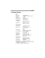
Summary of Contents for Raystar 114
Page 3: ......
Page 15: ...12 Raystar 114 ...


