background image

Item

Description

1

Band saw

2

Saw blade

3

Fence

4

Fairing block with cutting guide attached

5

Dead rise angle

6

Table tilt

Retain the top half of the fairing block as this will provide a level surface inside the hull to tighten
the nuts against.

8. Check the bottom half of the block against the hull to ensure a good fit.

Ensure that the block runs parallel to the centerline of the vessel.

9. If there are gaps between the block and hull then use an appropriate file to shape the block until

a precision fit is achieved.

Band saw fence to blade distance

The table below identifies the distance to set the band saw’s fence from the blade depending on the
dead rise angle of your hull. If you have used a cutting guide then you will need to add the cutting
guide’s width to the fence to blade distance.

Important:

When using a cutting guide you must add the width of your cutting guide to the stated fence to
blade distance for your selected dead rise angle.

Item

Description

1

Blade

2

Distance (fence to blade)

3

Fence

Installation

31

Summary of Contents for HYPERVISIONT HV-300 Series

Page 1: ... 2019 Raymarine UK Limited 87391 2 Document number 03 2019 Date English en US Installation instructions HV 300 HYPERVISIONTM ...

Page 2: ......

Page 3: ...or design patents pending Fair Use Statement You may print no more than three copies of this manual for your own use You may not make any further copies or distribute or use the manual in any other way including without limitation exploiting the manual commercially or giving or selling copies to third parties Software updates Check the Raymarine website for the latest software releases for your pr...

Page 4: ......

Page 5: ... displays 13 2 5 Parts supplied 14 Additional parts supplied 14 Chapter 3 Installation 17 3 1 Tools required 18 Tools required for fairing block preparation 18 Anti fouling 19 3 2 Pre installation test 21 Testing the transducer 21 3 3 Selecting a location 22 Warnings and cautions 22 Location requirements 22 EMC installation guidelines 26 3 4 Mounting 27 Dead rise angle 27 Mounting the transducer 3...

Page 6: ...aning 49 6 3 Re applying anti fouling paint 50 Chapter 7 Technical support 51 7 1 Raymarine product support and servicing 52 7 2 Learning resources 54 Chapter 8 Technical specification 55 8 1 Technical specification 56 Physical specification 56 Environmental specification 56 HyperVision technical specification 56 Conformance specification 57 Chapter 9 Spares and accessories 59 9 1 Spares 60 9 2 Ac...

Page 7: ... or otherwise attempt to access internal components unless specifically instructed in the documentation provided Warning Switch off power supply Ensure the vessel s power supply is switched OFF before starting to install this product Do NOT connect or disconnect equipment with the power switched on unless instructed in this document Warning Transducer operation Only test and operate the transducer...

Page 8: ...d electronic equipment which contains materials components and substances that may be hazardous and present a risk to human health and the environment when WEEE is not handled correctly Equipment marked with the crossed out wheeled bin symbol indicates that the equipment should not be disposed of in unsorted household waste Local authorities in many regions have established collection schemes unde...

Page 9: ...mation Chapter contents 2 1 Product documentation on page 10 2 2 Applicable products on page 11 2 3 Product overview on page 12 2 4 Required additional components on page 13 2 5 Parts supplied on page 14 Document and product information 9 ...

Page 10: ...uctions for the Sonar app on your display 81384 Element HyperVision Advanced Operation instructions Includes advanced operation instructions for the Sonar app on your display 81388 Operation instructions For detailed operation instructions for your product refer to the documentation that accompanies your display All product documentation is available to download from the Raymarine website www raym...

Page 11: ...vessel hulls with a dead rise from 0 up to 25 Part number Description A80604 HV 300TH HyperVision all in one thru hull plastic transducer T70448 HV 300THP P and HV 300THP S HyperVision thru hull plastic transducers supplied as a port and starboard pair R70725 HV 300THP P HyperVision port side thru hull plastic transducer R70726 HV 300THP S HyperVision starboard side thru hull plastic transducer Do...

Page 12: ... hull transducers are recommended for fiberglass and metal hulls and should not be used on vessels with wooden hulls The transducer has a 0 tilted element The supplied fairing block should be cut to match the dead rise angle of your hull HyperVision transducers are capable of producing sonar images for RealVision 3D Hyper 1 2 MHz RealVision 3D Standard 350 kHz SideVision Hyper 1 2 MHz SideVision S...

Page 13: ...device Refer to p 13 Compatible displays for a list of compatible products For longer cable runs a transducer extension cable will also be required Refer to p 39 HV 300 transducer extension cable for suitable cables Compatible displays Compatible displays are listed below Part number Description E70532 Element 7 HV E70534 Element 9 HV E70536 Element 12 HV Document and product information 13 ...

Page 14: ...e list below Retain the packaging and documentation for future reference Item Description 1 Anti rotation nut 2 Hull nut 3 Anti rotation washer 4 Fairing block 5 Documentation pack 6 Anti rotation bolt 7 Transducer with fitted cable Additional parts supplied The following additional cables are supplied when ordering a split pair set of transducers T70448 HV 300THP P and HV 300THP S 14 ...

Page 15: ...ing a split pair of transducers to a HyperVision compatible display Cable length 0 3 m 0 98 ft 2 1 x Extension cable 4 m 13 1 ft In a split pair transducer configuration extends the single end of the Y cable adapter Document and product information 15 ...

Page 16: ...16 ...

Page 17: ...Chapter 3 Installation Chapter contents 3 1 Tools required on page 18 3 2 Pre installation test on page 21 3 3 Selecting a location on page 22 3 4 Mounting on page 27 Installation 17 ...

Page 18: ... 44 mm 1 3 4 in wrench or suitable adjustable wrench for hull nut 4 Half round file 5 Drill bit for pilot holes 6 9 mm 11 32 in drill bit for anti rotation hole 7 Marine grade sealant 8 32 mm 1 1 4 in hole cutter for transducer stem 9 Adhesive tape Tools required for fairing block preparation The tools below are required to identify hull dead rise angle and to cut the fairing block 18 ...

Page 19: ...ent the build up of organic growth which can reduce transducer performance Important Before applying water based anti fouling paint check that local environmental rules and regulations do not prohibit the use of anti fouling paint Never use copper based anti fouling paint as this can impact transducer performance Never use ketone based anti fouling paint as this can attack the transducer s plastic...

Page 20: ... You should clean your transducer regularly and re apply anti fouling paint every 6 months or sooner depending on how rapidly organic growth builds up For guidance on transducer cleaning refer to 6 2 Transducer cleaning For instructions on re applying anti fouling paint refer to 6 3 Re applying anti fouling paint 20 ...

Page 21: ...erformed the startup wizard is displayed Transducer selection is part of the boat details options in the startup wizard 4 Open a Fishfinder Sonar app on your display 5 If required select the relevant transducer from the Transducer settings tab Menu Transducer Transducer 6 Check that accurate depth and temperature readings are displayed 7 If you experience difficulties obtaining readings then conta...

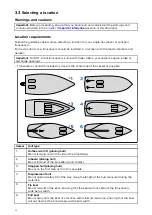
Page 22: ...ngine intake or discharge openings Transducers should be installed as close to the center line of the vessel as possible Vessel Hull type 1 Outboard or I O planing hull Mount forward and to the side of the propeller s 2 Inboard planing hull Mount forward of the propeller s and shaft s 3 Stepped hull planing hull Mount on the first step as far aft as possible 4 Displacement hull Mount approximately...

Page 23: ...ws of rivets Transducers should be installed in a location where no load will be applied to the transducers during launching lifting trailering and storage of the boat Transducers must be installed in the correct orientation with the anti rotation bolt closest to the stern of the vessel Additionally a direction arrow pointing to the bow is embossed on the transducer When installing split pair tran...

Page 24: ...ositions that are at least 300 mm 12 inches below the water line Transducers should be installed in a location where there is sufficient clearance inside the hull to fit the nut and have at least 100 mm 4 in of headroom to allow for withdrawal Cored fiberglass hull mounting It is recommended that the transducer is mounted in a non cored section if installation in a cored section is required then t...

Page 25: ...o the transducer is HV 300TH 6 m 19 69 ft HV 300THP S and HV 300THP P 2 m 6 5 ft A 4 m 13 12 ft HyperVision transducer extension cable A80562 is available It is recommended that a maximum of one cable extension is used Note When ordering the split pair transducer system pack T70448 a 0 3 m 0 98 ft Y splitter cable A80605 and a 4 m 13 12 ft extension cable A80562 are also supplied Nut sizes Hull nu...

Page 26: ...it are At least 1 m 3 3 ft from any equipment transmitting or cables carrying radio signals e g VHF radios cables and antennas In the case of SSB radios the distance should be increased to 2 m 6 6 ft More than 2 m 6 6 ft from the path of a radar beam A radar beam can normally be assumed to spread 20 degrees above and below the radiating element The product is supplied from a separate battery from ...

Page 27: ...ine 3 Dead Rise Angle 4 Parallel with waterline The dead rise angle should be measured on the outside of the hull using an angle finder or similar device Cutting guide You can use a bespoke cutting guide to help you guide your fairing block through the band saw You can create an L shaped cutting guide by joining to pieces of wood together The pieces need to be the same length or longer than the Fa...

Page 28: ...plied Cutting the fairing block The fairing block must be cut to the angle and shape of your hull as shown below Example port and starboard dead rise angles Item Description 1 Vessel hull viewed from the rear 2 Cut for starboard side fairing block installation 3 Cut for port side fairing block installation 28 ...

Page 29: ...ce to blade table added to the width of your cutting guide if used Using the fence to blade table measurements ensures that the cut will be made at an appropriate place on the fairing producing 2 equally sized parts 4 Position the fairing block against the fence so that the top face of the fairing block is closest to the fence Important When installed the pointed end of the fairing must point towa...

Page 30: ...e acceptable cutting area of the fairing Acceptable cutting area Important Only cut in the area shown colored in the above illustration Do NOT cut in the hatched areas shown above 6 Recheck steps 1 to 5 7 Cut the fairing block Band saw cutting 30 ...

Page 31: ...ween the block and hull then use an appropriate file to shape the block until a precision fit is achieved Band saw fence to blade distance The table below identifies the distance to set the band saw s fence from the blade depending on the dead rise angle of your hull If you have used a cutting guide then you will need to add the cutting guide s width to the fence to blade distance Important When u...

Page 32: ... 0 27 in 11 13 1 mm 0 52 in 24 6 2 mm 0 24 in 12 12 6 mm 0 50 in 25 5 6 mm 0 22 in Mounting the transducer The transducer should be mounted following the steps below Important Only perform the installation with your vessel out of the water Do NOT lift or suspend the transducer using its cable Ensure that the transducer body is supported during installation Do NOT remove the label attached to the t...

Page 33: ...the transducer stem and anti rotation bolt 4 Remove the fairing block from the hull 5 Drill a pilot hole in the center of the location marked out for the transducer stem When drilling holes in hulls that have a dead rise ensure that holes are drilled straight up and not at the angle of your hull 6 Drill the stem hole using a 32 mm 1 1 4 in hole cutter 7 Using a half round file and or sandpaper ens...

Page 34: ...m debris 20 Apply a continuous thick bead of marine grade sealant all around the perimeter and across the top of the top face of the bottom half of the fairing block where it will meet the hull 21 Apply a thick bead of marine grade sealant all around the edges of the holes in the hull 22 Guide the transducer cable up through the stem hole in the hull 23 Guide the transducer stem and anti rotation ...

Page 35: ...e edges of the applied surfaces 36 Remove any excess marine grade sealant 37 Ensure that the marine grade sealant has fully cured Refer to the sealant manufacturer s instructions for curing times 38 Unless local environmental regulations prohibit apply a water based anti fouling paint to the bottom face of the transducer ensuring all of the externally exposed transducer surfaces are coated and the...

Page 36: ...nt as this can attack the transducer s plastic damaging the transducer Paint your transducer using a brush do not use a spray can or a sponge roller as these methods can cause tiny air bubbles to be incorporated in the paint which will also reduce transducer performance The anti fouling paint should be applied in a thin and even coat covering all externally exposed transducer surfaces You should c...

Page 37: ...Chapter 4 Connections Chapter contents 4 1 General cabling guidance on page 38 4 2 Cable routing on page 39 4 3 Making connections on page 40 Connections 37 ...

Page 38: ...long the run Strain relief Use adequate strain relief for cabling to ensure that connectors are protected from strain and will not pull out under extreme sea conditions Cable shielding Ensure that cable shielding is not damaged and that all cables are properly shielded Caution Transducer cable Do NOT use the transducer cable to lift or suspend the transducer always support the transducer body dire...

Page 39: ... transom then you should use the supplied escutcheon plate to cover the hole Secure the cable at regular intervals using the supplied cable clips Any excess cable should be coiled up at a convenient location HV 300 transducer extension cable For best performance cable runs should be kept to a minimum However for some installations it may be necessary to extend the transducer cable A 4 m 13 12 ft H...

Page 40: ...s switched off 2 Ensure that the device being connected to the unit has been installed in accordance with the installation instructions supplied with that device 3 Ensuring correct orientation push the cable connector fully onto the corresponding connector on the unit 4 Turn the locking collar clockwise to secure the cable 40 ...

Page 41: ...Chapter 5 System checks and troubleshooting Chapter contents 5 1 Operation instructions on page 42 5 2 Troubleshooting on page 43 System checks and troubleshooting 41 ...

Page 42: ...tions For detailed operation instructions for your product refer to the documentation that accompanies your display All product documentation is available to download from the Raymarine website www raymarine com manuals 42 ...

Page 43: ...bles ensuring connections are secure clean and free from corrosion replace if necessary 5 With the product under load using a multi meter check for high voltage drop across all connectors fuses etc this can cause the Fishfinder applications to stop scrolling or the unit to reset turn off replace if necessary Damaged or fouled transducer Check transducer condition ensuring it is not damaged and is ...

Page 44: ... fuses etc this can cause the Fishfinder applications to stop scrolling or the unit to reset turn off replace if necessary Vessel speed too high Slow vessel speed and recheck Bottom too shallow or too deep The bottom depth may be outside of the transducers depth range move vessel to shallower or deeper waters as relevant and recheck Poor problematic image Possible causes Possible solutions Targets...

Page 45: ... using a water based anti fouling paint Damaged transducer cable Check that the transducer cable and connection is free from damage and that the connections are secure and free from corrosion Turbulence around the transducer at higher speeds may affect transducer performance Slow vessel speed and recheck Interference from another transducer 1 Turn off the transducer causing the interference 2 Repo...

Page 46: ...46 ...

Page 47: ...Chapter 6 Maintenance Chapter contents 6 1 Routine checks on page 48 6 2 Transducer cleaning on page 49 6 3 Re applying anti fouling paint on page 50 Maintenance 47 ...

Page 48: ...g mechanisms are properly engaged Note Cable checks should be carried out with the power supply switched off Warning High voltage This product contains high voltage Adjustments require specialized service procedures and tools only available to qualified service technicians There are no user serviceable parts or adjustments The operator should never remove the cover or attempt to service the produc...

Page 49: ...fe Take care not to scratch the surface of the transducer as this can impact transducer performance Do NOT use harsh cleaning solvents such as acetone as this will damage the transducer Follow the guidance below to clean growth from your transducer use a soft cloth and a mild household cleaning detergent to clean mild growth build up use a scouring pad such as a green Scotch Brite pad and a mild h...

Page 50: ... re application of the anti fouling paint should be performed using suitable washdown facilities which ensures paint particles do not enter the water and impact aquatic life Take care not to scratch the transducer face as this may impact transducer performance 1 Remove your vessel from the water 2 Clean your transducer ensuring all organic growth is removed 3 Remove any flaking anti foul paint 4 U...

Page 51: ...Chapter 7 Technical support Chapter contents 7 1 Raymarine product support and servicing on page 52 7 2 Learning resources on page 54 Technical support 51 ...

Page 52: ...m Tel 44 0 1329 246 932 United States US E Mail rm usrepair flir com Tel 1 603 324 7900 Web support Please visit the Support area of the Raymarine website for Manuals and Documents http www raymarine com manuals Technical support forum http forum raymarine com Software updates http www raymarine com software Worldwide support Region Contact United Kingdom UK EMEA and Asia Pacific E Mail support uk...

Page 53: ...iary E Mail support fi raymarine com Tel 358 0 207 619 937 Norway Raymarine subsidiary E Mail support no raymarine com Tel 47 692 64 600 Denmark Raymarine subsidiary E Mail support dk raymarine com Tel 45 437 164 64 Russia Authorized Raymarine distributor E Mail info mikstmarine ru Tel 7 495 788 0508 Technical support 53 ...

Page 54: ...vailable in English Training courses Raymarine regularly runs a range of in depth training courses to help you make the most of your products Visit the Training section of the Raymarine website for more information http www raymarine co uk view id 2372 Technical support forum You can use the Technical support forum to ask a technical question about a Raymarine product or to find out how other cust...

Page 55: ...Chapter 8 Technical specification Chapter contents 8 1 Technical specification on page 56 Technical specification 55 ...

Page 56: ...cation The following specification only applies to HyperVision products Power 1 2 MHz Hyper 1000 W 350 kHz Standard 700 W 200 kHz Conical high CHIRP sonar 100 W Frequencies 1 2 MHz CHIRP 350 kHz CHIRP 200 kHz CHIRP Channels Conical high CHIRP sonar RealVision 3D Hyper RealVision 3D Standard SideVision Hyper SideVision Standard DownVision Hyper DownVision Standard 200 kHz range Conical high CHIRP s...

Page 57: ...Conformance specification Conformance EN 60945 2002 IEC 28846 1993 EMC Directive 2014 30 EU Australia and New Zealand C Tick Compliance Level 2 Technical specification 57 ...

Page 58: ...58 ...

Page 59: ...Chapter 9 Spares and accessories Chapter contents 9 1 Spares on page 60 9 2 Accessories on page 61 Spares and accessories 59 ...

Page 60: ...9 1 Spares Description Part number HV 300THP P Thru hull plastic transducer R70725 HV 300THP S Thru hull plastic transducer R70726 HV 300TH HV 300THP P HV 300THP S fairing block R70741 60 ...

Page 61: ...9 2 Accessories Description Part number HyperVision transducer extension cable 4 m 13 12 ft A80562 HV 300THP P HV 300THP S Y splitter cable 0 3 m 0 98 ft A80605 Spares and accessories 61 ...

Page 62: ......

Page 63: ...ting the transducer 32 Testing 21 Installation tools 18 19 L LightHouse 3 Tips and Tricks 54 LightHouse Sport Compatible displays 13 Location requirements 22 M Maintenance 7 Mounting the transducer 32 O Operation instructions 10 42 P Parts supplied 14 Product overview 12 Product recycling WEEE 8 Product support 52 S Service Center 52 Servicing 7 Split pair cables 14 Strain relief See Cable protect...

Page 64: ......

Page 65: ......

Page 66: ...Raymarine Marine House Cartwright Drive Fareham Hampshire PO15 5RJ United Kingdom Tel 44 0 1329 246 700 www raymarine com a brand by ...

Reviews: