background image

100

A-Series display - User reference manual

8.1  Using Sirius Radio

To start using Sirius radio

1.  Press and hold the  

PAGE/MENU

 button.

2.  Select 

Sirius Satellite Radio

 from the options displayed.

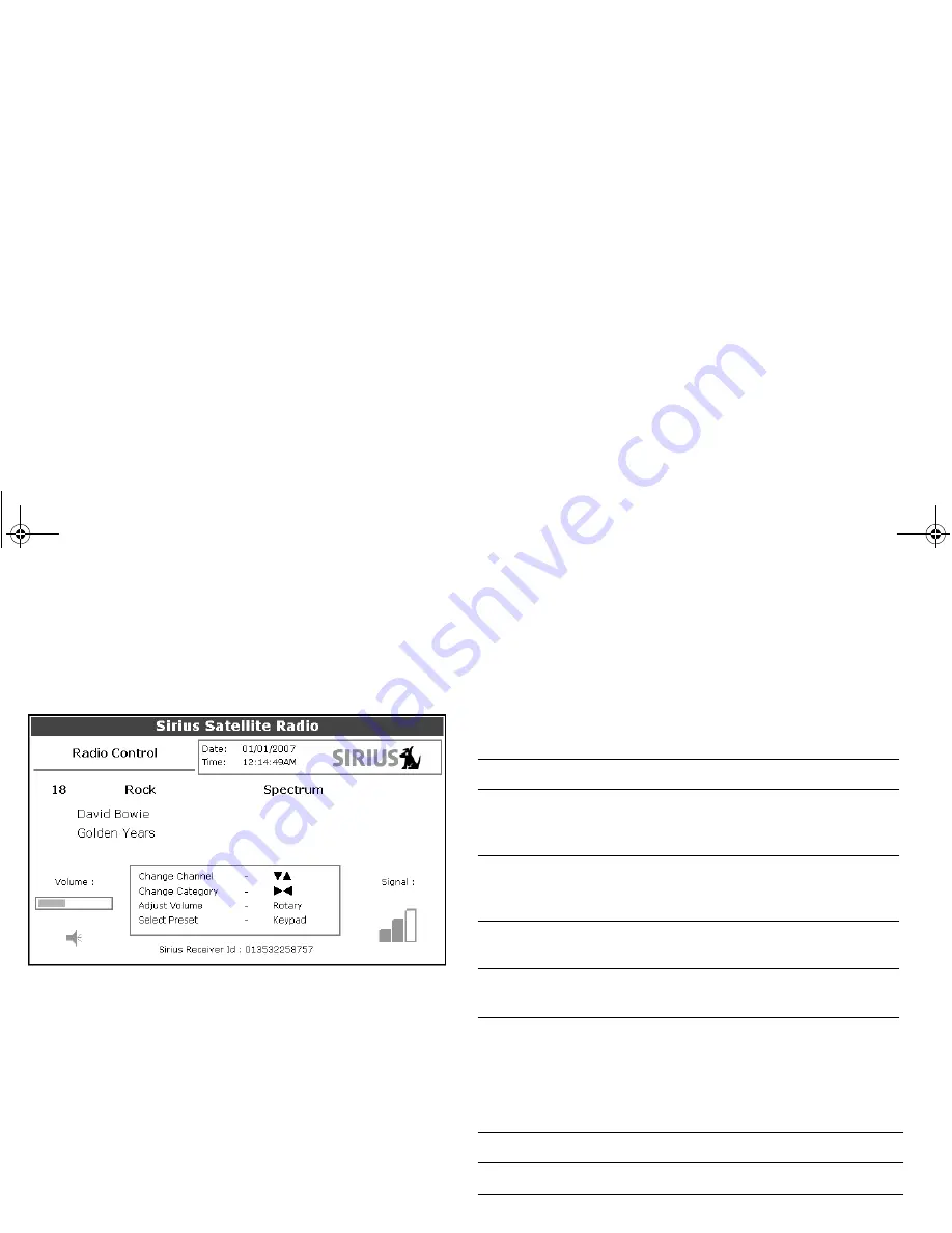
The Sirius Radio Control screen opens: 

Information contained on the Sirius Radio Control screen includes:

Current channel name, number and category

Play data for the current channel

Date and time

Receiver ID and signal strength

Use the softkeys and trackpad to control audio functions.
The toolbar gives you access to the functions outlined below.

Tuning to a channel

From the Sirius Control screen, you tune to channels using the 
trackpad or the alphanumeric keys.

MUTE ON/OFF

Controls the mute setting.

PRESETS

Displays a list of preset channels and the full 
channel list with modify options. Use the 
trackpad to scroll through the list of presets.

SETUP CHANNELS

Gives access to the Edit Presets, Edit Alerts, 
Edit Channel Access, Scan Channels 
softkeys.

ALERTS

Lets you set up an alert to tell you when favou-
rite songs or artists are played on any channel.

BROWSE

Scroll to view play data and to select channels, 
presets, or categories.

Trackpad up

Next channel.

Trackpad down

Previous channel.

81314-1_A Series Reference Guide.book  Page 100  Thursday, August 28, 2008  9:23 AM

Summary of Contents for A Series A50

Page 1: ...A Series Multi function display User reference manual A50 A50D A57D A70 and A70D models 81314 1_A Series Reference Guide book Page 1 Thursday August 28 2008 9 23 AM...

Page 2: ...GST AutoSeastate AutoTrim Bidata G Series HDFI LifeTag Marine Intelligence Maxiview On Board Raychart Raynav Raypilot Ray Talk Raystar ST40 ST60 Seaclutter Smart Route Tridata and Waypoint Navigation...

Page 3: ...Selecting a page set 25 Selecting an application page 25 Split screen pages 26 Emergencies and warnings 27 Man overboard 27 Alarms 27 Chapter 3 Waypoints 29 Introducing waypoints 30 Using Waypoints 31...

Page 4: ...m 60 Chart offset and cartography setup 60 Chart scale 62 Alarms 62 Chapter 5 3D chart application 63 Safety and system requirements 64 Safety 64 Requirements 64 3D chart operation 64 The controls 65...

Page 5: ...90 Storm Cast 90 Sea surface temperature SST 91 Canadian radar 91 Tracking storms 91 Tropical storm data 92 Lightning 92 Surface observation stations 92 City forecasts 92 Wind 93 Waves 93 Surface pre...

Page 6: ...114 AIS list 115 Full AIS data 115 AIS Options softkey 115 Messages and alarms 116 Safety messages 116 AIS alarms 116 Active alarm list 116 Chapter 11 Data and Engine monitors 119 System requirements...

Page 7: ...pter 14 Maintenance and troubleshooting 141 Safety 142 Routine checks 142 Cleaning 142 Resetting the system 143 Settings reset 143 Settings and data reset 143 Troubleshooting 144 Installation and disp...

Page 8: ...8 A Series display User reference manual 81314 1_A Series Reference Guide book Page 8 Thursday August 28 2008 9 23 AM...

Page 9: ...contains no user serviceable compo nents Please refer all maintenance and repair to authorized Raymarine dealers Unauthorized repair may affect your warranty CAUTION CompactFlash cards When installin...

Page 10: ...s Multi media chart cards The A Series Multifunction Display is compatible with Navionics chart data You you can insert Navionics chart cards into the Com pactFlash card slot on the unit If your A Ser...

Page 11: ...r ship please take a few minutes to fill out the warranty registration card found in the box or visit www raymarine com and register on line It is important that you register your product to receive f...

Page 12: ...12 A Series display User reference manual 81314 1_A Series Reference Guide book Page 12 Thursday August 28 2008 9 23 AM...

Page 13: ...age 14 2 2 System overview on page 14 2 3 Applications on page 16 2 4 First time use on page 17 2 5 Controls on page 19 2 6 Operation on page 20 2 7 Additional screen information on page 22 2 8 Displa...

Page 14: ...ixel TFT 256 color sunlight viewable display and an internal high sensitivity GPS module A Series models A50 5 display GPS Chartplotter A50D 5 display GPS Chartplotter Fishfinder combination A57D 5 7...

Page 15: ...with NMEA 0183 e g for AIS or external GPS connection SeaTalkng D11238 2 Pilot Instrument SeaTalkng SeaTalk NMEA 0183 NMEA 0183 A Series display Sonar transducer Power IN SeaTalk devices ENTER CANCEL...

Page 16: ...avigate routes View details of nearby features services View details of boats equipped with AIS Measure distances and bearings See where the fish are Identify underwater objects View seabed structure...

Page 17: ...ange the required page set at any time See Displaying applications on page 25 To Select a page set at first time Power on 1 Use the trackpad Up Down keys to select the required Page Set 2 Press OK whe...

Page 18: ...uding any safety messages e g those received from AIS To turn the simulator ON or OFF 1 Press and hold the PAGE MENU button to display the setup menu 2 Use the trackpad up down keys to select System S...

Page 19: ...vious softkey or menu level WPTS MOB Press and release to display the waypoints softkeys Press again to place a waypoint at your boat s position Press and hold to place a Man Overboard MOB marker at y...

Page 20: ...not been moved for a short period of time it changes to a circle with a cross in it to make it easier to locate on screen The cursor is context sensitive when it is placed over an object e g a waypoi...

Page 21: ...minor misalignment of objects may occur where they cross the chart boundaries Display lighting and color Your display unit has two distinct color palettes for day or night operation You can also manua...

Page 22: ...e lists Contain information you have added to the display s memory e g waypoints Highlight an entry using trackpad or rotary control to display related information Editable using soft keys Pop up mess...

Page 23: ...ves you a continuous readout centred on your current heading or course over ground COG Arrows at either end of the bar indicate current steer direction When displayed it replaces the databar and is al...

Page 24: ...is available See also For full details of the setup menus and available settings refer to System Setup and Customizing on page 125 Dialog boxes Dialog boxes are provided for you to edit or enter data...

Page 25: ...oups called page sets Selecting a page set To select a page set 1 Press and hold the PAGE MENU button to display the setup menu 2 Choose the Select Page Set option Selecting an application page Once y...

Page 26: ...the active window 1 Press ACTIVE to toggle active status between windows the red border moves to highlight the active window To toggle between split and single window views 1 In a multiple window view...

Page 27: ...information including bearing range and position are displayed in the databar Navigation functions are suspended and no new GOTO or route functions are selectable Motion mode on the chart application...

Page 28: ...t in the route starts when you cancel the alarm External alarms are triggered by equipment that is connected to your A Series system but which are not part of the system e g AIS When you cancel an ext...

Page 29: ...ns how to use them for navigation with your A Series Multifunction Display Chapter contents 3 1 Introducing waypoints on page 30 3 2 Using Waypoints on page 31 3 3 Waypoint groups on page 35 81314 1_A...

Page 30: ...in a waypoint list Waypoints can be created in any application and displayed on the chart and fishfinder windows Chart waypoints On a 2D chart all waypoints are shown The active waypoint i e the one...

Page 31: ...ess the WPTS MOB button Creating waypoints You can place a waypoint at the cursor your boat s position a point specified by latitude and longitude or Loran TD co ordinates To set up your system for Lo...

Page 32: ...n you navigate to a waypoint the data is sent to your autopilot The waypoint to which you are navigating is the active waypoint Note Autopilots must be compatible and connected to the A Series display...

Page 33: ...tically assigns it a name symbol and group You can change these details and add comments if required This is particularly useful if you are managing large groups of waypoints The default waypoint symb...

Page 34: ...waypoints You can move the position of any waypoint except an active one There are two methods of moving a waypoint either by dragging it into a new position using the cursor or changing its co ordina...

Page 35: ...6 Select ERASE ALL WAYPOINTS 7 Confirm the deletion 3 3 Waypoint groups All new waypoints are automatically placed in a group called My Waypoints To make waypoints easier to manage you can organize t...

Page 36: ...ups When you delete a waypoint group the group name and all the associated waypoints are erased from the system If a group contains one or more waypoints that you want to keep move these waypoints out...

Page 37: ...quirements on page 38 4 2 The chart on page 39 4 3 Navigating to a specific point on page 41 4 4 Creating a route on page 42 4 5 Following a route on page 44 4 6 Editing routes on page 45 4 7 Course d...

Page 38: ...n experience in using your display unit Before you use the chart application make sure you have read and understand Chapter 3 Waypoints WARNING Navigation aid This product is intended to serve only as...

Page 39: ...art card is present the A Series will automatically use the most recent cartography for the display Chart range Chart orientation Motion mode Status bar Current position Carto graphic object Active wa...

Page 40: ...around the chart and display the area required at an appro priate scale use the track pad and range in out buttons Note Remember that the cartographic detail available on the chart will vary according...

Page 41: ...TIONS softkey to open the waypoint list 3 Select the waypoint you want to navigate to 4 Press the GOTO WAYPOINT softkey To stop navigating to a waypoint 1 Press the STOP GOTO softkey Maintaining a vie...

Page 42: ...immediately Quick Route Build and save a route for later use in which case the route is stored in the route list Convert a track into a route To build and follow a route using new waypoints 1 Press t...

Page 43: ...t from the new route list 1 Use the trackpad to highlight the waypoint to be removed from the route list 2 Press the REMOVE WAYPOINT softkey The remaining waypoints will renumber accordingly To abando...

Page 44: ...waypoint and the system automatically activates the reverse follow route function To follow a route in reverse order 1 Press either the GOTO or ROUTES softkey 2 Press the FOLLOW ROUTE OPTIONS softkey...

Page 45: ...waypoint list appears 3 Use the trackpad to highlight the position for the added waypoint in the right hand column 4 Use the trackpad to highlight the waypoint you want to add to the route in the left...

Page 46: ...TES softkey 2 Press the REVIEW AND EDIT ROUTES softkey The routes list appears 3 Use the trackpad to highlight the route to be erased 4 Press the ERASE ROUTE softkey Timed routes Details of all routes...

Page 47: ...our course by steering in the direction indicated by the arrows Resetting cross track error Whilst following a route or navigating to a waypoint it is possible to restart the cross track error XTE Thi...

Page 48: ...2 Press the STOP TRACK softkey 3 Press SAVE TRACK or DISCARD TRACK depending on what you want to do with the track Creating a route from a track To create a route from a current track This method take...

Page 49: ...m 4 9 Measuring distance range and bearing The A Series provides a number of tools to measure distance range and bearing Using the cursor to measure distance and bearing You can determine the exact po...

Page 50: ...save your settings Ruler The chart application includes a ruler which accurately measures the distance and bearing between two points To use the ruler 1 Position the cursor at the start point of the m...

Page 51: ...turn it on or off as required 5 Press OK to save your settings Vectors and arrows The vectors and arrows are a chart presentation layer They present system data with relation to your vessel on the cha...

Page 52: ...rientation options North Up N Up This is the default mode with the chart static and orientated with true north to the top of the screen As your boat s heading changes the boat symbol rotates according...

Page 53: ...yed on the chart For example you may wish to hide certain features if there are many objects displayed in a small geographic area Show Hide waypoints routes and tracks There are a number of options to...

Page 54: ...y Set Up Menu 4 12 Journey planning Your electronic charts contain a number of features to help you plan your journey Note Certain features require additional or upgraded cartography available within...

Page 55: ...o choose to view the animation continuously or step through it in increments To view animated tide and current data 1 Use the trackpad to move the cursor over the required tidal or current diamond 2 P...

Page 56: ...the system is in bathymetric mode but does not have data Details of objects and features Many objects shown on the chart have detailed information associ ated with them Some of this information is sh...

Page 57: ...rt name or the first few characters of the port name 5 Press SEARCH 6 If the search returns more than one port select the port you are interested in 7 Select your service 8 Press the VIEW DETAILS soft...

Page 58: ...list 5 Press the VIEW PHOTO soft key To overlay aerial photography 1 Press the PRESENTATION soft key 2 Press the CHART LAYERS soft key 3 Toggle AERIAL OVERLAY to ON or OFF as required 4 Use the trackp...

Page 59: ...r Length Specify a time period for drawing COG and heading vectors 3 Mins 6 Mins Infinite Vector Width Sets the width of the COG and HEADING chart vector lines Thin Normal Wide Record Vessel Track By...

Page 60: ...to a maximum of 1000m An indicator in the chart window tells you when chart offset is enabled Restore chart offset to zero when you begin using a chart with the correct georeference Please report cha...

Page 61: ...tion Routing Data ON OFF FUNCTION OPTIONS Marine Features Cables nature of seabed points tide station current stations and port information ON OFF Land Features The cartographic features that are disp...

Page 62: ...ever there could be some misalignment of objects which cross the chart boundary in this area Alarms With the appropriate equipment installed and powered up the fol lowing alarms may be triggered in th...

Page 63: ...ity is poor Navigation functions are available in the 3D chart Chapter contents 5 1 Safety and system requirements on page 64 5 2 3D chart operation on page 64 5 3 Using the standard and 3D charts tog...

Page 64: ...be relied upon as complete or accurate as their use and availability may vary locally It is your responsibility to use caution sound judgement official government charts notices to mariners and prope...

Page 65: ...nd Planning modes You can choose to view the 3D chart application in one of two modes Active action mode Planning mode Active mode is the default mode when entering the 3D chart application To select...

Page 66: ...g mode Changing the view There are four view options to choose from forward aft port and starboard The current option is highlighted on the toolbar and displayed in the status bar AFT PRT PRT ROTATE 1...

Page 67: ...t exaggeration 1 Press the PRESENTATION softkey 2 Press the 3D VIEW OPTIONS softkey 3 Press ADJUST EXAGGERATION 4 Use the trackpad to set your level of exaggeration 5 Press OK Press CANCEL at any time...

Page 68: ...n about setting up a page set to view two applications together see Split screen pages on page 26 3D view locator The view locator is a polygon displayed on the standard chart which outlines the bound...

Page 69: ...o heading range or position in either 2D or 3D charts are reflected in both windows If the 2D chart view for the current window is set to SYSTEM any changes made in a chart window will be reflected in...

Page 70: ...e system setup menu For information on using the system setup menu refer to Setup menus on page 24 The 3D chart menu gives the following options Standard 3D image 3D image with aerial overlay D8848_1...

Page 71: ...en on page 72 6 2 How the fishfinder works on page 72 6 3 Interpreting the Fishfinder image on page 73 6 4 Fishfinder Pre set operation on page 74 6 5 Changing the depth range on page 78 6 6 Presentat...

Page 72: ...s into the water and measures the time it takes for the sound wave to travel to the bottom and back The returning echoes are affected by bottom structure and by any other objects in their path for exa...

Page 73: ...peed The fishfinder s reading of the bottom and other objects is affected by your relative speed Slower speeds return flatter more horizontal marks as your speed increases the image will tend to thick...

Page 74: ...ation on reducing clutter and background noise see Gain and power on page 79 6 4 Fishfinder Pre set operation The fishfinder provides you with four preset configurations available on the default toolb...

Page 75: ...der image Set the zoom factor to a pre defined level or adjust it manually Reposition the zoomed portion of the image to a different point in the display When the range increases the area shown in the...

Page 76: ...d bottom shift The Bottom Lock function applies a filter to flatten the image of the seabed and make any objects on or just above it easier to discern This feature is particularly useful for finding f...

Page 77: ...ottom of the window To display the A Scope image 1 Press the SELECT VIEW softkey 2 Use the track pad up down to select A SCOPE display mode 3 Press the A SCOPE MODE softkey to select the required disp...

Page 78: ...manual or auto range mode 1 Open the Range Adjust toolbar 2 Toggle to AUTO or MAN on the RANGE softkey 3 Press OK Range shift The DSM automatically adjusts the display to keep the bottom in the lower...

Page 79: ...mum of background noise while you cruise to your fishing spot Only the strongest echoes are displayed Medium is a slightly higher gain setting that displays more detail High provides the most detail b...

Page 80: ...ttom signal strength Manual If you wish to manually adjust the power to suit current condi tions you can adjust the power level between 0 and 100 in 10 increments Lower power levels are normally used...

Page 81: ...rsor depth the depth and the distance from your boat marked by the cursor is indicated in the data bar at the top of the screen This performs in a similar way to a VRM but without lines VRMs to indica...

Page 82: ...percent age the slower the image will scroll The default is manual adjustment with a full speed scroll 100 To select the scroll mode and speed 1 Open the Fishfinder Setup Menu 2 Set your preferred val...

Page 83: ...her information on waypoints operation refer to Waypoints on page 29 6 8 Fishfinder alarms There are a number of alarm messages associated with the fish finder application Fish Alarms sound when a tar...

Page 84: ...To open the Setup Frequency Preset screen 1 With a fishfinder window active press and hold the PAGE MENU button 2 Select Configure Frequency Presets Manual frequency selection If you select a frequen...

Page 85: ...kHz Auto Gain Auto High 75 9ft 75 200 kHz Auto Gain Auto High D6833 3 Standard fishfinder image The standard fishfinder image displays the bottom as a combination of features mud sand fish targets et...

Page 86: ...an integrated speed transducer Frequency Calibration Hides the setup menu and brings up a set of soft keys to tune the transducer frequencies Depth Offset waterline Offset represents the depth of the...

Page 87: ...for your current position or areas that you are planning to visit This chapter should be read in conjunction with your Sirius Weather Receiver handbook Chapter contents 7 1 System requirements on page...

Page 88: ...n on installing and commissioning a weather receiver see the SR50 Weather Receiver Installation Guide 7 2 Using Sirius Weather Creating a weather page A weather application window is not included in t...

Page 89: ...ing waypoints The waypoint button operates as normal when a weather window is active but you need to make the chart window active to see any waypoints created Weather symbols The system has a number o...

Page 90: ...gory 1 5 Tropical storm Tropical disturbance tropical depression Storm Tracks symbols 1012 High low pressure blue red Cold front blue Warm front red Occluded front purple Stationary front red blue Tro...

Page 91: ...typhoons The display shows the path the storm has taken its current and forecast position the wind radii for its current position only and its current direction and speed of travel Color Intensity mm...

Page 92: ...rface observation stations You can view current or historical weather data at surface observa tion stations City forecasts The Cities option gives you access to details of city weather fore casts Fore...

Page 93: ...option gives you wave period wave direction and wave height data Wave height is displayed in 16 levels 3 7 kts 8 12 kts 13 17 kts 18 22 kts 23 27 kts 28 32 kts 33 37 kts 38 42 kts 43 47 kts 48 52 kts...

Page 94: ...option has not been selected Ranging or panning causes the animation to restart The animation stops if you press any of the ACTIVE PAGE DATA WPS MOB or PAGE MENU buttons or if you close the window con...

Page 95: ...ackpad to scroll through the report You can set the range for the watchbox alert to OFF 50 150 300 500 and ALL using the weather setup menu Any watchbox outside of the selected range will not trigger...

Page 96: ...ay the watchbox data 7 5 Troubleshooting 7 6 Weather application setup With a weather window active the Weather Setup Menu is available from the system Setup menu To open the Weather Setup Menu 1 With...

Page 97: ...etails the Weather ID obtained from Sirius and keyed in on your display as advised Wind Symbol Graphic used for wind symbol Arrow Barb Marine Watchbox Alerts Enables alert when watchbox is issued OFF...

Page 98: ...98 A Series display User reference manual 81314 1_A Series Reference Guide book Page 98 Thursday August 28 2008 9 23 AM...

Page 99: ...d you can use the A Series system to control satellite radio broadcasts Refer to the SR50 documentation for installation information Chapter contents 8 1 Using Sirius Radio on page 100 8 2 Parental lo...

Page 100: ...ed below Tuning to a channel From the Sirius Control screen you tune to channels using the trackpad or the alphanumeric keys MUTE ON OFF Controls the mute setting PRESETS Displays a list of preset cha...

Page 101: ...he category you want to browse 4 Press OK Scanning channels The Scan function automatically tunes to all channels in turn To scan channels 1 Press the SETUP CHANNELS softkey 2 Select SCAN CHANNELS 3 U...

Page 102: ...n a channel to a preset 1 Select an unused preset number from the Preset List 2 Press the ASSIGN NEW CHANNEL softkey 3 Select the target channel from the Channel List 4 Press the ASSIGN TO PRESET soft...

Page 103: ...e channel you want to block 4 Press the CHANNEL ENABLED LOCKED to highlight LOCKED 5 Repeat steps 3 4 for each additional channel you want to block 6 When you have blocked all the channels you want pr...

Page 104: ...e list or switch the favorites alert off You can also mark a channel or song as a favourite by pressing the ASSIGN TO ALERT softkey while scanning When alerts are turned on and the system detects one...

Page 105: ...editerranean Sea The North Sea coastal areas around Japan and areas around the North American continent This chapter should be read in conjunction with your Navtex receiver handbook Chapter contents 9...

Page 106: ...lect Navtex Messages and open the Navtex Message List 3 Press the SETUP ALERTS softkey 4 Select the appropriate category and toggle its status to the required setting 9 3 The Navtex message window Onc...

Page 107: ...y the date and time the message was received DATE with the most recent message at the top If required you can sort the list by station identifier STN or by mes sage category CAT To sort the message li...

Page 108: ...108 A Series display User reference manual 81314 1_A Series Reference Guide book Page 108 Thursday August 28 2008 9 23 AM...

Page 109: ...on is used to provide fast automatic and accurate hazard awareness and collision avoidance data This chapter should be read in conjunction with your AIS receiver handbook Chapter contents 10 1 Backgro...

Page 110: ...S display Not all AIS receivers will decode all information and not all of the Class A vessels input all of the required AIS data For example some inexpensive AIS Class B receivers do not decode and o...

Page 111: ...S AIS is a selectable layer of the chart application To switch AIS layer on 1 With a chart window active press the PRESENTATION softkey 2 Press the CHART LAYERS AND DATA then the CHART LAYERS softkeys...

Page 112: ...layed Vectors can be displayed for each target These vectors indicate the direction of travel and rate of turn of the vessel and the distance it will travel over a specified period of time COG SOG vec...

Page 113: ...y 2 Press the AIS OPTIONS soft key The AIS options dialog box appears 3 Select the Own Vessel Safe Zone and set the radius of your boat s safe zone Safe zone alarm The safe zone alarm is an audible wa...

Page 114: ...eriod of time Graphical representation of heading and direction of turn To switch AIS vectors on or off 1 Highlight the AIS target for which you want to display vectors 2 Toggle to your desired settin...

Page 115: ...S DATA softkey AIS Options softkey The AIS OPTIONS softkey provides a number of configuration settings D9092_1 Parameter Options Vector Length The time period specified for drawing length of vectors 0...

Page 116: ...o the dangerous target alarm the system generates an alarm when a dangerous target becomes lost this happens if the AIS signal from a tracked vessel is not received for more than 20 seconds When the c...

Page 117: ...softkey 2 Acknowledge the message at your AIS unit Note Alarms remain active until they are acknowledged on the AIS unit Removing the message or adding it to the Alarm list on your A Series system do...

Page 118: ...118 A Series display User reference manual 81314 1_A Series Reference Guide book Page 118 Thursday August 28 2008 9 23 AM...

Page 119: ...ystem requirements on page 120 11 2 Data application on page 120 11 3 Engine monitor on page 121 11 4 Customizing data panels on page 123 See also www raymarine com for information about compatible en...

Page 120: ...e can include Compatible Raymarine instruments Compatible engines Other equipment and instruments connected via NMEA0183 or SeaTalkng 11 2 Data application The data application page is shown as a data...

Page 121: ...ine monitor window Set the number of engines and the maximum tachometer range to reflect your particular vessel For information about how to do customize page sets see Page sets on page 126 Vessel pos...

Page 122: ...rial gallons or US gallons are defined in the System Setup Menu under Units Setup Engine monitor alarms The engine monitor triggers an alarm over NMEA SeaTalkng when a problem is detected If this occu...

Page 123: ...1 Press and hold the PAGE MENU button and select Panel Setup Menu 2 Select the cell you want to assign data to 3 Press the SELECT DATA softkey 4 Select the data type and format 5 Press OK To split ce...

Page 124: ...124 A Series display User reference manual 81314 1_A Series Reference Guide book Page 124 Thursday August 28 2008 9 23 AM...

Page 125: ...ents 12 1 Page sets on page 126 12 2 Databar and Compass on page 126 12 3 Compass Setup on page 127 12 4 GPS status on page 127 12 5 System wide settings on page 129 See also For instructions on how t...

Page 126: ...ey EDIT PAGE SET RENAME PAGE SET RESET TO DEFAULT PAGES 5 Follow the on screen instructions for the option you selected 6 Press OK 12 2 Databar and Compass To configure the databar 1 Press and hold th...

Page 127: ...the GPS Status option in the Setup Menu Data groups Data abbreviations in brackets VESSEL Vessel position Ves Pos Course over ground Speed over ground COG SOG Heading Speed Wind velocity made good VM...

Page 128: ...ion of 1 0 Satellite differential system Select the satellite group s appropriate to your area using the Other Set Up softkey WAAS United States EGNOS Europe MSAS Japan GAGAN India Note The EGNOS MSAS...

Page 129: ...Dead reckoning will only provide the correct MOB posi tion if the required COG SOG and Tide data are available Your boat and the MOB are subject to the same tide and wind effects Assuming that the req...

Page 130: ...llows you to set up a password to protect access to your waypoint and route databases MENU ITEM OPTIONS Date Format Displays date as day month year or month day year mm dd yy dd mm yy MENU ITEM OPTION...

Page 131: ...ils of distress DSC messages are displayed on screen ON OFF SeaTalk Alarms When set to enabled all SeaTalk system alarms are received and displayed on the chartplotter Enabled Disabled Data Master Whe...

Page 132: ...9mins 00h00m Alarm Clock Switches the alarm clock on or off OFF ON Alarm Clock Time If the Alarm Clock is set to ON an alarm is triggered when the time you specify is reached 00 01 24 00hrs 00 00 Temp...

Page 133: ...any target meets the sensitivity level and is within the Shallow Fish Limit and Deep Fish Limit that you specify OFF ON Shallow Fish Limit Specifies the lower value for the Fish Alarm Depth LImit 2ft...

Page 134: ...receiver MENU OPTION OPTIONS Soft key Autohide Controls whether the toolbar is automatically hidden if not used for a period of 10 seconds Pressing any key re displays it OFF ON Cursor Autohide Contro...

Page 135: ...y with Navionics chart cards and also act as a storage device for routes waypoints and other data Chapter contents 13 1 Card use and information on page 136 13 2 Storing and retrieving data on page 13...

Page 136: ...system software Saving data Enables waypoints route and track data to be saved for use on other equipment such as a personal computer Note Raymarine recommends the use of SanDisk CF memory cards Othe...

Page 137: ...setup menu may result in a system crash and or loss of data To remove a CompactFlash card with the unit powered ON 1 Press and hold the PAGE MENU button to display the System Setup Menu 2 Select Remo...

Page 138: ...o save by pressing the appropriate softkey To retrieve information from a CF card 1 Insert the appropriate card 2 Press and hold the PAGE MENU button to display the System Setup Menu 3 Select the ARCH...

Page 139: ...at any point press STOP TRANSFER 13 4 Password protection If required you can use password protection to control access to your waypoint and route databases Once you have set up a pass word it must be...

Page 140: ...e waypoint and route functions remains available until you restart your system To change the password 1 Select Change Password on the Waypoint Password Setup menu Enabling and disabling password prote...

Page 141: ...ers the following Chapter contents 14 1 Safety on page 142 14 2 Routine checks on page 142 14 3 Resetting the system on page 143 14 4 Troubleshooting on page 144 14 5 Contacting Raymarine on page 146...

Page 142: ...olvent detergent on the screen Screen coating A coating is applied to the plastic screen of your display This makes it water repellent and prevents glare To avoid damaging this coating the recommended...

Page 143: ...ings reset Settings and data reset After applying either of the above resets your system resets and returns you to the power on procedure Settings reset When you apply a settings reset all system menu...

Page 144: ...after referring to the table contact your local Raymarine dealer national service agent or Raymarine Technical Services for further advice Always quote the product serial number which can be found on...

Page 145: ...ck that the instrument interface is operating correctly Check the SeaTalk NMEA connection to the display unit Check all SeaTalk NMEA system cables are free from damage and corrosion Problem Solution B...

Page 146: ...is appropriate for your unit you should contact the Technical Support Department to verify your requirements Technical Support For technical support call 1 603 881 5200 ext 2444 Raymarine Technical Su...

Page 147: ...oose for your Raymarine unit please contact the Customer Services Department prior to placing an order Worldwide Please contact the authorized dealer in the relevant country as listed on the website a...

Page 148: ...au Navionics UK PO Box 38 Plymouth PL9 8YY England Tel 44 0 1752 204735 Fax 44 0 1752 204736 e mail sales navionics co uk 14 7 Contacting Sirius For questions about the Sirius Marine Weather Service...

Page 149: ...r with or pre loaded on a Raymarine TM device or storage media Your warranty with respect to the Data and Related Materials is provided by Raymarine plc or its affiliate and is set forth in the writte...

Page 150: ...SI Corporation WSI nor Sirius Satellite Radio Inc Sirius makes any representations or warranties with respect to the reliability predictive value or accuracy of the information contained within the Se...

Page 151: ...NTAL ELEMENT OF SIRIUS AGREEMENT TO PROVIDE THE SERVICE TO SUBSCRIBER SUBSCRIBER MAY HAVE GREATER RIGHT THAN DESCRIBED UNDER HIS OR HER STATE S LAW B EXCEPT FOR WILLFUL MISCONDUCT ON THE PART OF WSI A...

Page 152: ...152 81314 1_A Series Reference Guide book Page 152 Thursday August 28 2008 9 23 AM...

Page 153: ...81314 1_A Series Reference Guide book Page 153 Thursday August 28 2008 9 23 AM...

Page 154: ...l 44 0 23 9269 3611 Fax 44 0 23 9269 4642 www raymarine com Raymarine Inc 21 Manchester Street Merrimack New Hampshire 03054 USA Tel 1 603 881 5200 Fax 1 603 864 4756 www raymarine com 81314 1_A Serie...

Reviews: