Rayleigh Instruments RI-ENERGYFLOW-3P-15 Series User Manual Download Page 13

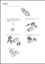
Figure 3-4 mounting the inverter

3.4  Mounting procedure

Setp1: Drill 4 Fix Ø11 holes in the wall according to the dimensions.
Step2: Fix the wall mounting bracket on the wall with 4 expansion bolts in accessory bag. 
Setp4: Place the inverter on the wall-mounted bracket and install the fix screw.

fix screw

3.5  Electrical connection  

3.5.1  Connection to the grid (AC output)   

Connect the inverter to the grid as follows:
1)Strip off N/L1/L2/L3 cables as figure 3-5: 

Diameter ranges 

15-25mm

12mm

50mm

6-10mm²

Remark

Protective layer

Length of stripped off

Insulate layer

Cross section of ac cables

Description

A

B

C

D

No.

Figure 3-5 Strip off N/L1/L2/L3 cables

2) Strip off PE cable as figure 3-6:

1) Add breaker or fuse to AC side, the specification should be more than 1.25 times of rated AC output 
    current.
2) The PE line of inverter should be connected to the earth, make sure the impedance of neutral wire 
    and earth wire less than 10 ohm.
3) Disconnect the breaker or fuse between the inverter and the utility.
4) All inverters incorporate a certified internal Residual Current Device (RCD) in order to protect against 
    possible electrocution and fire hazard in case of a malfunction in the PV array, cables or inverter. 
    There are 2 trip thresholds for the RCD as required for certification (IEC 62109-2:2011). The default 
    value for electrocution protection is 30mA, and for slow rising current is 300mA.

A

C

D

B

Telephone  :  +44  (0)  1245  428500        

Email : [email protected]

11

Summary of Contents for RI-ENERGYFLOW-3P-15 Series

Page 1: ...428500 Email sales rayleigh com 3P SERIES 15 Solar Inverter User Manual RI ENERGYFLOW 3P SERIES 15 www rayleigh com Rayleigh Instruments Limited Raytel House Cutlers Road South Woodham Ferrers Chelmsf...

Page 2: ......

Page 3: ...3 Installationandstartup 3 1Packageinformation 3 2Installationenvironment 3 3Installationposition 3 4Mountingprocedure 3 5Electricalconnection 3 6StartingtheInverter 4 UserInterface 4 1Ledandkey 4 2LC...

Page 4: ...roughout the manual important information is shown at different levels depending on the character of the information as shown here Safety information important for human safety Violation of warnings m...

Page 5: ...al Keep in mind that the inverter has two voltage carrying sides the PV input and the AC grid Disconnecting the inverter Always disconnect the AC line rst Afterwards disconnect the PV lines Note that...

Page 6: ...y be mandatory in some countrie The selection of PV string output should be based on the optimum utilization of the invested capital compared to the expected annual energy yield from the system This o...

Page 7: ...r Factor cos Output THDi Rated Output Efficiency Max Efficiency Euro Efficiency MPPT Efficiency 6000W 7500W 9000W 12000W 1000V 2 Integrated 140 950V 15000W 18000W 22500W 160V 1 1 16A 16A 4000W 4400VA...

Page 8: ...C 62109 2 EN 61000 3 2 EN 61000 3 3 EN 61000 3 11 EN 61000 3 12 EN 61000 6 2 EN 61000 6 3 IEC 61000 4 16 IEC 61000 4 18 4 29 Protection DC Insulation Monitoring Input Reverse Polarity Protection Anti...

Page 9: ...777 Philippines power Grid meet Grid standards IEC61727 60HZ spec Sri Lanka power Grid Grid voltage range 160 290V Grid frequency range 47 53HZ Thailand power Grid Thailand power Grid Grid voltage ran...

Page 10: ...e still contains electricity so please wait for at least 5 minutes to ensure the capacitors completely release the energy and inverter is not electri ed Note Inverters must be installed by quali ed pe...

Page 11: ...method and mounting location must be suitable for the inverter s weight and dimensions 2 Mount on a solid surface 3 Select a well ventilated place sheltered from direct sun radiation Figure 3 3 Distan...

Page 12: ...edure Setp1 Drill 4 Fix 11 holes in the wall according to the dimensions Step2 Fix the wall mounting bracket on the wall with 4 expansion bolts in accessory bag Setp4 Place the inverter on the wall mo...

Page 13: ...ed AC output current 2 The PE line of inverter should be connected to the earth make sure the impedance of neutral wire and earth wire less than 10 ohm 3 Disconnect the breaker or fuse between the inv...

Page 14: ...ting terminal is ush with the surface of the terminal and the crimping screw torque is 2 0 0 1N m 6 Insert the main part of AC connector into the terminal and hear a click sound 7 Use a wrench to tigh...

Page 15: ...herwise it will cause damage to inverter 3 5 2 Connection to PV string DC input Disassembly the inverter from the Grid 1 Use a screwdriver to press against the unlocked position and hold the wire nut...

Page 16: ...RS485 connecting cables not exceed 1000m 2 Communication lines must be separated from other power lines to avoid communications interference Relay C G N CT _ white black DRM S0 S1 S2 S3 S4 S5 S6 S7 CO...

Page 17: ...will turn into self check mode and the LCD panel will display the remaining time of connect simultaneously After the inverter turn into normal mode it feed electrical energy into grid and LCD panel w...

Page 18: ...wer W Ipv2 A Power W Vac A V Power W Iac A A Power W Fac Hz Power W E today KwH Power W E total KwH Power W SN NO Moudle Firmware M S Country Event list Power W Setting Power W Fault code1 Power W Lan...

Page 19: ...n long in order to enter the setting menu Press pushbutton less than 1 sec several times until you reach the AutoTest Italy menu You need to set the inverter country to CEI 0 21 before testing Press p...

Page 20: ...will automatically run the test until the screen shows Test end Click Read to read the test value and click Export to export the test report After click Read button interface will show the test result...

Page 21: ...y terms of factory you need to supply us with the following information and documentation regarding the faulty unit Product Model No e g R1 8K DS and the serial Number e g 8700831201211006 Copy of the...

Page 22: ...M 2 Check whether the AC side has contacts with earth Grid Faults Fault OVR Fault UVR Fault OFR Fault UFR 1 Wait for 5 minutes if the grid returns to normal PV inverter automatically restarts 2 Make s...

Page 23: ...nge OCPV OCPV2 OCIGrid SciCommLose SpiCommLose BusFault CPU ADFault IGridDevice PLLFault AutoTestFail PVCon gFault FanError LCD display Permanent Fault Fault 1 Disconnect all PV or PV from solar panel...

Page 24: ...ou have any further technical questions about our product please contact us Head Office Rayleigh Instruments Limited Raytel House Cutlers Road South Woodham Ferrers Chelmsford Essex CM3 5WA United Kin...

Reviews: