background image

19 


5. Start&Stop  
 

5.1 Start the Inverter  


To start up the Inverter, the following steps must be strictly followed:  
 
1. Switch the grid supply main Switch (AC) ON first.  
2. Switch the DC switch ON. If the voltage of PV arrays is higher than the start-up voltage, the inverter will turn 
on. The LED status indicator will light.  
3. When both the DC and the AC sides supply to the inverter, it will be ready to generate power. Initially, the 
inverter will check both its internal parameters and the parameters of the AC grid, to ensure that they are within 
acceptable  limits.  At  the  same  time,  the  green  LED  will  flash  and  the  LCD  displays  the  information  of 
INITIALIZING.  
4. After 20-300 seconds (depending on local requirement), the inverter will start to generate power. The green 
LED will be on continually and the LCD displays GENERATING.  


 Do not touch the surface when the inverter is operating. It may be hot and cause burns. 


5.2 Stop the Inverter 


To stop the Inverter, the following steps must be strictly followed: 
 1. Switch the Supply Main Switch (AC) OFF.  
 2. Wait 30 seconds. Switch the DC Switch OFF. All the LEDs of the inverter will be off in one minute. 


6.  Operation  
 

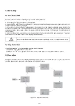
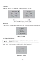
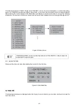
During the normal operation, the display alternately shows various status information (see Figure 6.1). Screens 
can also be scrolled manually by pressing the UP and DOWN keys.  


Figure 6.1 Operation Overview 


Summary of Contents for RI-ENERGY 3.0D

Page 1: ...yleigh Instruments Limited Head Office RaytelHouse CutlersRoad SouthWoodhamFerrers Chelmsford EssexCM35WA UK E Sales Rayleigh com Rayleigh Instruments Limited SP Z o o European Office Ul Aleje Jerozol...

Page 2: ...2...

Page 3: ...nt Panel Display 8 3 2 LED Status Indicator Light 8 3 3 Keypad Optional 8 3 4 LCD Optional 9 4 Installation 9 4 1 Select a Location for the Inverter 9 4 2 Mounting the Inverter 10 4 3 Electrical Conne...

Page 4: ...LOW MIDI 3 0D 3 6D 4 0D 4 6D 5 0D 6 0D Figure 1 1 Front and side view Figure 1 2 Bottom side view Object Description DVC class 1 PV1 PV2 DVC C 2 AC OUTPUT DVC C 3 DRM DVC A 4 CT DVC A 5 COM DVC A 1 2...

Page 5: ...RM connector 1 2 CT connector 1 3 WiFi GPRS Stick 1 4 1xCT and com cable 1 2 Safety instructions Please read the safety instructions in this manual Throughout the manual it is assumed that the reader...

Page 6: ...portant for the protection of property Violation of this type of information may cause damage and loss of property RoHS Useful additional information or Tips and Tricks on specific subjects ROHS Mark...

Page 7: ...ed personnel are allowed to repair or modify the inverter To ensure optimum safety for user and environment only the original spare parts available from your supplier should be used Functional safety...

Page 8: ...n the indicator light is green it indicates the operation state Light Status Description ON Alarm or fault condition is detected ON The inverter is operating properly Flashing Grid Connected countdown...

Page 9: ...direct sunlight or raining To avoid overheating ambient air temperature must be considered when choosing the inverter installation location Rayleigh Instruments recommends using a sunshade to minimise...

Page 10: ...e 4 3 Inverter wall mounting Please see Figure 4 4 and Figure 4 5 for instructions on mounting the inverter The inverter shall be mounted vertically The steps to mount the inverter are listed below 1...

Page 11: ...ure 4 5 Figure 4 5 Wall Mount Bracket 5 Use M5 16 screws in the accessory to lock the inverter to the mount bracket 4 3 Electrical Connections 4 3 1 Connect PV side of inverter The electrical connecti...

Page 12: ...ion Range Recommended value Industry generic PV cable model PV1 F 4 0 6 0 12 10AWG 4 0 12AWG Table 4 1 DC cable The steps to assemble the DC connectors are listed as follows I Strip off the DC wire fo...

Page 13: ...lick will confirm the connection Figure 4 11 Connect the DC Connectors to the Inverter 4 3 2 Connect grid side of the inverter For all AC connections 4 10mm 105 XJ cable is required to be used Please...

Page 14: ...threaded sleeve over the AC cable c d Insert the crimped conductors L N and PE into the corresponding terminals and tighten the screw with a hex key wrench screwdriver size 2 5 1 2 2 0Nm Ensure that...

Page 15: ...e right side of inverter Prepare OT terminals M5 Use proper tooling to crimp the lug to the terminal Figure 4 18 Connect the external grounding conductor When an earth fault occurs the machine cannot...

Page 16: ...urrent A Current for protection device A 3 0D 380 15 20 3 6D 380 15 20 4 0D 380 15 20 4 6D 380 15 20 5 0D 380 15 20 6 0D 380 15 20 Table 4 4 Rating of PV OCPD 4 3 5 Inverter monitoring connection The...

Page 17: ...optional This inverter has integrated export limitation functionality To use this function a CT must be installed if use the CT please reference the picture below The CT should be fitted around the l...

Page 18: ...d to support demand response mode DRM This function is for the inverter that complies with AS NZS 4777 2 2015 standard RI ENERGYFLOW MIDI single phase inverter fully complies with all DRM A 6P termina...

Page 19: ...the green LED will flash and the LCD displays the information of INITIALIZING 4 After 20 300 seconds depending on local requirement the inverter will start to generate power The green LED will be on c...

Page 20: ...the ESC key to access to the Main Menu there are three submenus in the Main Menu see Figure 6 3 Figure 6 3 Main Menu 6 1 Setup Technicians Only To access this area is for fully qualified and accredit...

Page 21: ...he following information You can also continue to access the next menu level Password can be changed through item 11 Figure 6 5 Setup menu POWER FACTOR mode is selected by default and QU WAVE or other...

Page 22: ...ot and cause burns Turn off the inverter refer to Section 5 2 and wait for a cool down period before any maintenance or cleaning operation The LCD and the LED status indicator lights can be cleaned wi...

Page 23: ...t of working temperature F13 Heatsink Temperature High 1 Disconnect PV input and cool down the inverter then restart the inverter to see if it is back to normal operation 2 Please check environmental...

Page 24: ...0D 3 6D 4 0D 4 6D 5 0D 6 0D DC Input Data Max DC power W 4050 4860 5400 6210 6750 8100 Max Rated DC voltage V 600V 380V Min Start DC voltage V 120V 100V MPPT voltage range V 80V 550V Number of MPPT 2...

Page 25: ...legible Otherwise Rayleigh Instruments has the right to refuse to honour the quality guarantee Conditions After replacement unqualified products shall be processed by Rayleigh Instruments The custome...

Page 26: ......

Page 27: ...ted Raytel House Cutlers Road South Woodham Ferrers Chelmsford Essex CM3 5WA UK Email sales rayleigh com W www Rayleigh com Rayleigh Instruments Limited SP Z o o European Office Ul Aleje Jerozolimskie...

Reviews: