2-AXIS DEFLECTION UNITS
Translation of the original manual
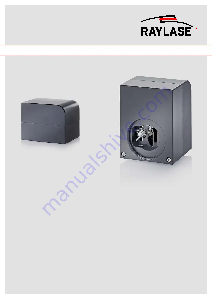
MINISCAN II
MINISCAN II-07, MINISCAN II-10, MINISCAN II-14, MINISCAN II-20
Page 1: ...2 AXIS DEFLECTION UNITS Translation of the original manual MINISCAN II MINISCAN II 07 MINISCAN II 10 MINISCAN II 14 MINISCAN II 20...
Page 2: ...ibed in this manual and the information it contains without prior notification All rights reserved Duplication of this manual including extracts particularly by photocopying scanning or photographing...
Page 3: ...2 7 Required protection measures 11 2 8 Behaviour in case of destroyed ZnSe lenses 11 3 PRODUCT DESCRIPTION ______________________________12 3 1 Items included accessories and spare parts 12 3 2 Gene...
Page 4: ...___________________28 7 1 Safety when uninstalling 28 7 2 Uninstalling the deflection unit 28 8 STORAGE ____________________________________________29 9 TRANSPORTATION ________________________________...
Page 5: ...volved in developing installing uninstalling or using a laser system with a RAYLASE deflection unit If the deflection unit is sold on this manual or an authorised copy must be passed on with it 1 2 Di...
Page 6: ...conditions of business These can be viewed at https www raylase de en terms and conditions html RAYLASE GmbH has no obligation to repair any defects occurring under the following circumstances If the...
Page 7: ...sers with wavelengths of 193 nm to 11 000 nm and an input aperture of 7 9 14 or 20 mm 2 2 Foreseeable misuse Foreseeable misuse includes the following Use of the deflection unit outside the specificat...
Page 8: ...laser radiation is in the visible spectral range 400 nm to 700 nm Short exposure times up to 0 25 s are not dangerous to the eyes provided the beam cross section is not reduced by optical instruments...
Page 9: ...ces matt and dark surfaces can also reflect laser radiation and that a laser beam reflected several times can still be dangerous In addition the deflection unit can be destroyed by back reflection X2...
Page 10: ...5 2 Measures to prevent uncontrolled escape of laser radiation If the mirrors in the deflection unit are destroyed the laser beam no longer exits the deflection unit at the intended beam output but r...
Page 11: ...the coating and the relative size of the decomposed area of the lens surface mean that even in the worst cases the resulting radioactive exposure levels are normally well below the limits set out in...
Page 12: ...n unit Software package 3 2 General description 3 2 1 Deflection unit The deflection unit can be used to deflect a laser beam in the X and Y direction This results in a two dimensional area in which t...
Page 13: ...UCT DESCRIPTION 2017 RAYLASE GmbH MINISCAN II MN102 en v1 0 3 13 1 Beam input 4 Beam output 2 Galvanometer scanner with mirror 5 Processing area 3 Galvanometer scanner with mirror Fig 2 Functional pri...
Page 14: ...figure must be compensated by the deflection unit Distortion caused by XY deflection Distortion caused by F Theta lens Distortion caused by XY deflection with F Theta lens 3 2 3 Connections The MINIS...
Page 15: ...meters The parameters are specified in the type code on the rating plate Further information on the specifications on the rating plate can be found on the Internet at https www raylase de _Resources P...
Page 16: ...ich the product is designed Serial number Year of production month The series and serial number are also used to identify the product The protective seal warns against unauthorised opening of the prod...
Page 17: ...rad IP Code 54 Emission sound pressure level 70 dB A 1 Drift per axis 2 After 30 min warm up at constant ambient temperature and process stress Remark All angles optical 3 6 2 Power supply Voltage 15...
Page 18: ...bjective kg approx 0 8 approx 0 8 approx 1 6 approx 2 2 Dimension L x W x H mm 100 77 79 5 100 77 79 5 134 98 93 5 145 116 103 5 3 6 5 2 Dynamic behaviour Type MINISCAN II 07 MINISCAN II 10 MINISCAN I...
Page 19: ...D SUB 25 M PIN Signal PIN Signal 1 X COMMAND 14 X COMMAND 2 SIGNAL GND 15 X POSITION 3 SIGNAL GND 16 Y POSITION 4 SIGNAL GND 17 Y COMMAND 5 Y COMMAND 18 nc 6 nc 19 nc 7 nc 20 nc 8 nc 21 nc 9 VSS 22 VS...
Page 20: ...3 PRODUCT DESCRIPTION 2017 RAYLASE GmbH MINISCAN II MN102 en v1 0 3 20 Signal source Deflection unit Signal source Deflection unit Fig 4 Standard input Fig 5 Differential input...
Page 21: ...X CHANNEL 4 I Y CHANNEL 17 I Y COMMAND 5 nc 18 nc 6 O HEAD STATUS 19 O HEAD STATUS 7 nc 20 nc 8 nc 21 nc 9 VSS 22 VSS 10 VSS 23 GND Input 11 GND Input 24 GND Input 12 VSS 25 VSS 13 VSS I Diff input n...
Page 22: ...limitation shutdown on overcurrent line protection Make sure that the power supply does not exceed the specified low voltage During all work on the electrical power supply and the electrical systems...
Page 23: ...ns contact RAYLASE 4 4 Installing the lens 1 Carefully remove the protective cover on the deflection unit beam output and the protective cover on the lens 2 Check the deflection unit and the lens for...
Page 24: ...er to the specifications in the technical data for details C2 05 0 4 Make sure that no water is splashed onto the deflection unit C2 05 0 5 Check whether the laser wavelength corresponds to the specif...
Page 25: ...itable mirrors To do this refer to the deflection unit rating plate and compare the details with the application see page16 Signage 4 Check that the lens has been mounted into the deflection unit beam...
Page 26: ...accidentally switched on again 3 Clean the deflection unit housing with a soft lint free duster 4 If there is more severe dirt moisten the cloth with a non aggressive cleaning solution e g soap soluti...
Page 27: ...ace with clean and oil free compressed air Note that the compressed air in workshops may contain oil particles and in this case is unsuitable for cleaning optics 4 Moisten a suitable lens cleaning clo...
Page 28: ...use injuries The deflection unit should be installed by two people wearing suitable safety shoes 7 2 Uninstalling the deflection unit 1 Switch off the laser system and secure it against accidentally b...
Page 29: ...STORAGE 2017 RAYLASE GmbH MINISCAN II MN102 en v1 0 3 29 8 STORAGE The deflection unit must be stored in a dust free location and under the specified ambient conditions see page 17 Ambient conditions...
Page 30: ...amage due to improper transportation During transportation or shipping of the deflection unit there is a risk of it being damaged Seal the deflection unit in a dust proof container before transportati...
Page 31: ...10 DISPOSAL 2017 RAYLASE GmbH MINISCAN II MN102 en v1 0 3 31 10 DISPOSAL Observe the applicable regulations for disposal of the deflection unit...
Page 32: ...oblem Possible cause Remedy Processing quality is poor Electrical energy supply defective Processing parameters incorrect Deflection unit unsuitable for selected application Processing quality has det...
Page 33: ...ction required instruction 11 Interface analogue 19 digital 21 Interfaces 19 Items included 12 L Laser area 9 Laser radiation 10 Laser system classification 8 Laser warning sign 16 Lens 26 Lens 23 M M...
Page 34: ...RAYLASE GmbH MINISCAN II MN102 v1 0 3 34 Transportation 30 Troubleshooting 32 U Uninstalling 28 Safety 28 W Warranty 6 Weight 17...
Page 35: ...H Wessling Germany 49 8153 8898 0 info raylase de China subsidiary RAYLASE Laser Technology Shenzhen Ltd Shenzhen China 86 755 2824 8533 info raylase cn USA subsidiary RAYLASE Laser Technology Inc New...