T415 Operation & Service Manual
800.392.2686
97
Maintenance
24
25
BLN-10197 • 520L0532 • April 2002
Series 45 Frame K and L Open Circuit Axial Piston Pumps
Service Manual
Minor repair
BLN-10197 • 520L0532 • April 2002
Series 45 Frame K and L Open Circuit Axial Piston Pumps
Service Manual
Minor repair
Reassembly
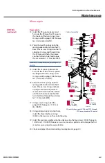
13. Install the PC spool, spherical end
first, into the PC bore. The PC spool is
the shorter of the two. Using a new
O-ring, install the plug (C103). Torque
to 11-14 N•m [8-10 lbf•ft].
14. Place the two PC springs onto the
spring guide and install into the PC
bore. Place a new O-ring onto the PC
adjustment screw and thread it into
the PC bore until flush, then make
another full turn. Install and torque
the set screw to 7-11 N•m [6-8 lbf•ft].
Note: For PC only controls, skip steps 15
and 16.
15. Install the LS spool, spherical end
first, into the LS bore. The LS spool is
the longer of the two. Using a new
O-ring, install the plug (C106). Torque
to 11-14 N•m [8-10 lbf•ft].
16. Place the two LS springs onto the
spring guide and install into the LS
bore. Place a new O-ring and back-
up rings onto the LS adjustment
screw and thread it into the LS bore
until flush, then make another full
turn. Install and torque the set screw
to 7-11 N•m [6-8 lbf•ft].
17. Using a new O-ring, install the
plug (C107). Torque to 11-14 N•m
[8-10 lbf•ft].
18. Using petroleum jelly to retain them,
install the three interface O-rings
CONTROL
(continued)
C117
C118
6mm
C116
C117
C114
C115
C113
C200
C138
6mm
C136
C135
C134
C133
C132
C103A
C112
C106A
C106
3/16 in
11-14 N•m
[8-10 lbf•ft]
C103
3/16 in
11-14 N•m
[8-10 lbf•ft]
C300 (4pl.)
5mm
15-18 N•m
[11-13 lbf•ft]
C102 (2pl.)
4mm
7-11 N•m
[6-8 lbf•ft]
P101 667
C107A
C107
3/16 in
11-14 N•m
[8-10 lbf•ft]
Control assembly
LS control shown; parts C106 and C112 through
C118 are not used on PC control
(C200) in the recesses on the control housing.
19. Install the control assembly onto the endcap using the four screws (C300). Torque to
15-18 N•m [11-13 lbf•ft]. Torque screws in a criss-cross pattern and re-torque the first
screw to ensure proper torque retention.
20. Check and adjust the control setting. See
Adjustments
, page 20.


