background image

Company Confidential


17


Raveon Technologies Corp. 


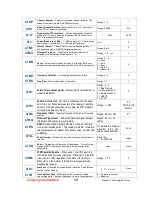
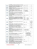
AT

LA


Listen Address 

– Configures the listen address for this unit. The 

unit will receive data if this listen address matches the destination 
address in a data transmission. FFFF to disable it.    

Range: 0000 - FFFF 

1234  

AT

MK


Address Mask 

– Configures local and global address space. 

Each digit may be a 0,1,2,3,4,5,6,7,8,9,A,B,C,D,E,or F.   In most 
applications, this is kept at FFFF.   

Range: 0000 - FFFF 

FFFF  

AT

MY


Unit Address 

– Configures the individual; address for this unit. 

Each digit may be a 0,1,2,3,4,5,6,7,8,9,A,B,C,D,E,or F.   Note: FF 
is interpreted as a group. See addressing section.  

Range: 0000 - FFFF 

1234  

AT

PE


Packet Error Display – 

Shows statistics to compute packet-

error rate.  Displays Packets Per Minute (PPM) and a running 
total.  


None (display PER) 
1 = reset counters 
2 = Stop PER display 

None 

AT

PO 

RF Power Output

.  Set or show the RF power output setting.  

Value is in percent, from 0% to 100%.  Use and RF wattmeter to 
confirm the power setting, and adjust the % accordingly to obtain 
the desired RF power level.  


0-100 

100 

AT

R0


Symbol Peak Deviation 

– Set the peak FM deviation of the 

transmit symbols.  Note: This can be a negative number to invert 
the modulation. 


Range: -1000 – 1000 

120** 

AT

R2 

Over-The-Air bit rate 

-  This is the data rate the radio uses to 

send data over the air. 

 All RF modems in the network must 

use the same over-the-air baud rate

.  Refer to section 

Error! 

Reference source not found.

 for information on how to set the 

OTA baud rate.


Range:


0 = 800 

5 = 9600 2L 

1 = 1200 

6 = 19200 4L 

2 = 2400 

7 =  5142 2L 

3 = 4800 

8 = 9600 4L 

4 = 8000 4L  9 = 2000 2L 

3 narrow 

AT

R5 

Preamble length 

– The number of bytes to send over-the-air in 

the pre-amble. 


Range: 3 - 255


5

**


(Varies based on 

data rate and 

radio type. 7 

typical)


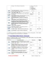
AT

RB 

Number of retries

.   If this modem does not get an ACK back 

when it sends data, this is the number of times it will re-transmit 
the packet and wait for an ACK.  0=disabled feature.  


Range:  0-99 

0  

(ACKs are not 

used) 

AT

RF 

RF Carrier Required 

– When enabled, there must be RF 

energy on the channel for the modem to output data.  
Streaming data mode only.  1-RF required. 0=ignore RF energy 
when receiving.  

Range: 0, 1  

0 (no RF 

required) 

AT

RV 


Disable Remote Access

 – When enabled (set to a 0), the 

modem will respond to over-the-air RPR requests, Pings, and 
over-the-air commands.  Default is OFF (1).   

0 = Remote Access on 
1 = Remote Access off 

AT

TT 

Max Packet Size – 

Set the maximum number of bytes in an 

over-the-air packet.  


1 - 512 

80 

AT

Xn 

Show or Configure the Repeat Table 

– Set the addresses that 

this unit will store-and-forward data to/from.  n = 1, 2, 3, or 4 
designating the entry in the table to show or edit.. 


Four parameters


aaaa bbbb cccc dddd  where 

aaaa=Source Address 

bbbb = S.A. Mask 

cccc = Destination Address 

dddd = D.A. Mask 

AT

XR 

Enable/Disable Store and Forward Repeating – 

0=disabled, 1 

– enabled.


0 or 1 

0 (Off) 

AT

XT 

Read/set repeater delay – 

Read or set the repeater delay.  This 

is the time between receiving a data packet, and the time the 
repeater will re-send it. 


PING 

Ping another modem.  Format is PING xxxx, where xxxx is 
the ID of the modem to ping. If remote access is enabled on 
xxxx, it will respond.  

XXXX 

REPEAT 

Turn Repeater feature on/off.  If 1, a quick way to enable 
repeating all packets. I f  0, disables the  repeat feature. 

0 (off) or 1 (on) 

RPR 

Remote Procedure Request.

  Used to request execution of a 

command on a remote mode (over the air).  See 

M8T System 

Protocol

 manual for information on using this feature. 


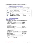
Summary of Contents for RV-M8T

Page 1: ...y Confidential 1 Raveon Technologies Corp RV M8T RV M8R Data Paging Radio Modem Technical Manual Version A7 September 2013 Raveon Technologies Corporation 2461 Impala Drive Carlsbad CA 92010 www raveo...

Page 2: ...Commands 14 6 1 General Command Common to Data Mode and Paging Mode 14 6 2 Data Modem Mode Related Commands 16 6 3 Paging Receiver Related Commands 18 6 4 Factory Default Settings 18 7 Using the M8T i...

Page 3: ...on 36 11 2 Calibration Commands 36 11 3 Center Frequency 37 11 4 TX Deviation 37 11 5 TX Modulation Balance 37 11 6 RX Carrier Detect 38 12 Troubleshooting 40 Symptom Unit will not receive 40 Symptom...

Page 4: ...g caps in a blasting area or in areas posted Turn off two way radio Obey all signs and instructions Potentially Explosive Atmospheres Turn off your radio prior to entering any area with a potentially...

Page 5: ...nge or higher data throughput It is also available in a receive only version called the M8R The M8R is the same electrical design and has the same features as the M8T except the transmit circuits are...

Page 6: ...er Features POCSAG decoder mode operates at 512 1200 and 2400 baud 1 3 programmable cap codes Promiscuous mode to receive all pages on the air Automatic and manual switching between numeric and alpha...

Page 7: ...1K load 0 0 2V Digital Input High 3 0V Digital Input Low 0 3V Enable input High 1 40V DC Input 8 13V volts DC 3 2 Transmitter Specifications RV M8T xx RF Power Output 100mW 2 0 W programmable Maximum...

Page 8: ...onnector Type 20 pin 2mm header DC Input 8 13V DC power draw RX mode 600mW DC power draw TX mode 2W 7W DC current draw standby mode 150uA IO Voltage Levels 3 3V digital logic RX and TX data Transparen...

Page 9: ...e data output 7 Enable I Low 7V to shut down the module High 2 5V to enable it 8 Sleep i CPU Sleep input 9 CTS O Clear to send output Indicates state of internal buffers 10 RTS I RTS input for serial...

Page 10: ...ycles up to 50 the module requires additional heat sinking If an external heat sink presses against the GND PAD are of the PCB the RF power transistor will run cooler and allow higher duty cycles 4 4...

Page 11: ...e M8T modem from unintentionally entering the Command Mode because of the pattern occurring in a stream of data entering the modem there must be a pause in the data stream before the as well as a paus...

Page 12: ...was 1234 the user would issue the following command ATDT cr and the modem will respond with 1234 CR LF OK CR LF To get on line help with a command enter the command and put a question mark in for the...

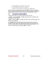
Page 13: ...into the M8T modem once the Command Mode is exited 5 6 Exiting the Command Mode There are three ways to exit the command mode They are 1 ATCN Issuing the ATCN The M8T radio will exit the command mode...

Page 14: ...mands have been received via the serial port within this time period in milliseconds modem returns to normal operation mode from Command mode If the CONFIG button inside the M8T is pressed this parame...

Page 15: ...The time in milliseconds for the serial port to time out When data is entering the serial port and this amo0unt of time passes with no more data the M8T will begin to transmit the data over the air R...

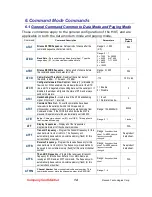
Page 16: ...tion 0 1 or 2 CHNUM Read number of channels This command will return the number of channels this product has 6 MODEL Read Model number Read the model number of the unit None M8T or M8R SHOW Show displ...

Page 17: ...umber of bytes to send over the air in the pre amble Range 3 255 5 Varies based on data rate and radio type 7 typical ATRB Number of retries If this modem does not get an ACK back when it sends data t...

Page 18: ...pager cap codes CC 1 12345 CC 2 1 CC 3 1 PM Promiscuous Mode Enable disable promiscuous mode 0 off 1 ON receive all paging messages 0 or 1 0 PR Pager Data Rate Parameter is 512 1200 or 2400 512 1200 2...

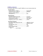
Page 19: ...ATMA 3 POCSAG Channel number selected 1 WMX WMX 0 OFF Paging Settings Over the air paging baud rate 512 baud Alternate protocol pin 15 1 POCSAG 512 Paging data format DF Auto detect Paging Cap Code 1...

Page 20: ...ta radio 3 POCSAG decode Pull input pin 15 high enabling the alternate protocol The factory default configuration is ATMA 3 and ATMT 0 7 1 Setting Cap Codes Cap Codes are the ID of the paging receiver...

Page 21: ...word into bits 30 11 0 9 are encoded as ASCII 0 9 Values beyond 9 in each nibble i e 0xA through 0xF are encoded as follows 0xA Reserved possibly used for address extension 0xB Character U urgency 0x...

Page 22: ...d the last codeword is filled with unprintable characters such as end of message end of text or null Null is the only character which can be incomplete The maximum length for a standard alpha numeric...

Page 23: ...ow to send 8 bit binary data 2 End of Text DLE ETX 16 0x10 3 0x03 ETX end of the data frame 8 0 4 ASCII hex Checksum Optional Variable 0 FFFF The 16 bit checksum of all the previous bytes starting wit...

Page 24: ...st user applications will seamlessly work using the M8T in its Packet Mode 6 Repeatable and Routable M8T packets are structured so that they may be repeated using a store and forward repeater and or r...

Page 25: ...that from the factory all M8T modems are configured to simply work Plug in power and connect to the serial port at 9600 baud and the modems will communicate on the default channel Change the channel...

Page 26: ...serial port data rate far in excess of the over the air rate the efficiency of the M8T in Packet Mode is approximately the same as other brand modems that cannot operate in a Packet Mode with the add...

Page 27: ...numbering The Group Number is set with the ATGP xx command where xx is the group number ATGP 0 disables group numbering and is the default way the M8T radio modem works If the Group Number is set to a...

Page 28: ...digit FF in the first two positions of the destination ID or in the last two positions of the destination ID will be interpreted as a broadcast and any modem with an ID that matches the two non FF di...

Page 29: ...default configuration All units have address 1234 and all modems will talk to all other modems with address 1234 Example 2 a configuration that won t work Sending to Destination Address 1236 Receivin...

Page 30: ...e radio can hear on the air REPEAT 0 disables store and forward repeating It is highly recommended that you use this method to configure your M8T as a repeater Important The Unit ID of the repeater mu...

Page 31: ...iable to E D C and G To solve this problem some of the M8T modems are configured as repeaters The still are able to send and receive data but they also will repeat data out to the modems that are out...

Page 32: ...Table may have up to 4 entries For example M8T B in the above example will have two entries in its Repeater Table The command to set the two entries is ATX1 1020 FFFF 1000 FFFF ARX2 1000 FFFF 1000 FF...

Page 33: ...ud rate on the end stations to be fairly slow ATBD x Thus when they receive a poll request there is a delay as they send data in out of their serial ports and during this delay the repeater can do its...

Page 34: ...channel 8 Transmit preamble 101010 pattern ML x Debug Message Level By default and at power on this level is set to 0 no debug messages 0 no debug or diagnostic messages 1 POCSAG and data reception r...

Page 35: ...dio modem will respond with a list of certain operation statistics that it maintains All statistics start counting at 0 The ATST 1 command can be used to reset all statistics back to 0 except the run...

Page 36: ...e only setting that may require adjustment is the center frequency After years of operation all crystals will age and change frequency slightly The ATR8 command is used to adjust the center frequency...

Page 37: ...el 3 Read the frequency offset with the ATR8 command 4 Adjust the frequency to the center of the channel with the ATR8 command You can use the U key and the D key to change the settings up and down on...

Page 38: ...f it is above this value Carrier Detect is asserted The pre set value may be change with the ATRA command Note Asserted means low Negated means high The CD pin will sit at about 3 3V when CD is not as...

Page 39: ...cessary for the serial terminal to wake from sleep or enter an appropriate mode to receive data In this mode the Carrier Detect handshaking line is nominally low and only goes high to signal that data...

Page 40: ...he M8 If the TX LED blinks the M8T is transmitting data Every time data enters the modem the TX LED should blink Solution 2 Verify that serial port timeout is OK The ATG0 command sets the number of mi...

Page 41: ...s the issue Symptom Modem appears dead Solution 1 Verify the power is on When the modem has good DC power the PWR LED will blink once per second If it is not blinking either the modem does not have po...

Page 42: ...Company Confidential 42 Raveon Technologies Corp 13 Mechanical A drawing is shown below...

Reviews: