5
Cab Component Installation: Install System Cables
31
CAB COMPONENT INSTALLATION
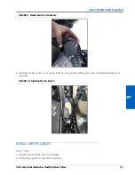
FIGURE 9. Master Switch in Enclosure
2. Install the master switch in a convenient location using either self-tapping screws or double sided tape (not
provided).
FIGURE 10. Installed Master Switch
INSTALL SYSTEM CABLES
HDU CABLE
1. Identify the HDU cable (P/N 115-4010-092).
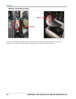
2. Remove the right-rear cover off the machine.
Summary of Contents for RS1/HDU
Page 4: ...Table of Contents ii RBR Enterprise Vector 300 LS Venturi LS RS1 HDU Installation Manual...
Page 8: ...CHAPTER 1 4 RBR Enterprise Vector 300 LS Venturi LS RS1 HDU Installation Manual...
Page 12: ...CHAPTER 2 8 RBR Enterprise Vector 300 LS Venturi LS RS1 HDU Installation Manual...
Page 13: ...2 Introduction Updates 9 INTRODUCTION...
Page 14: ...CHAPTER 2 10 RBR Enterprise Vector 300 LS Venturi LS RS1 HDU Installation Manual...
Page 26: ...CHAPTER 3 22 RBR Enterprise Vector 300 LS Venturi LS RS1 HDU Installation Manual...
Page 30: ...CHAPTER 4 26 RBR Enterprise Vector 300 LS Venturi LS RS1 HDU Installation Manual...
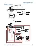
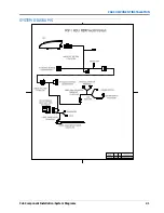
Page 45: ...Cab Component Installation System Diagrams 41 CAB COMPONENT INSTALLATION SYSTEM DIAGRAMS...
Page 46: ...CHAPTER 5 42 RBR Enterprise Vector 300 LS Venturi LS RS1 HDU Installation Manual...
Page 51: ...APPENDIX A 44 RBR Enterprise Vector 300 LS Venturi LS RS1 HDU Installation Manual...
Page 53: ...Index 46 RBR Enterprise Vector 300 LS Venturi LS RS1 HDU Installation Manual...

