background image

48

SERIAL PORT INFORMATION

To access serial port information:

1. Press Serial Port 

 on the CRX Settings screen. The Serial Ports - Port A 

window will open. Information for the Serial Port such as Baud Rate, Stop Bits, 

Parity, TX, and RX will display. If needed, select Detect Device to update the 

information.

2. To access information on other serial ports, select the desired Port from the left 

side of the window.

3. After viewing the Serial Port information, Press Accept 

.

GPS

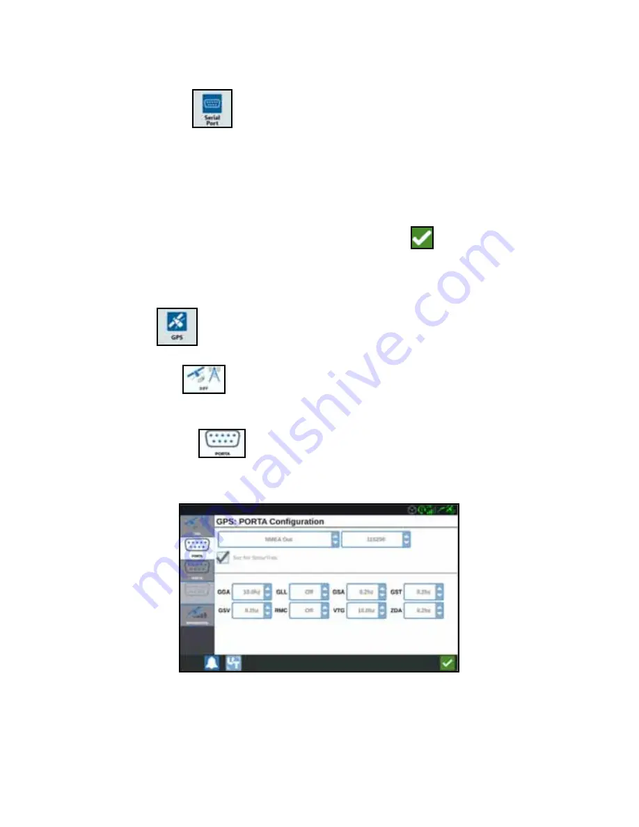
1. Press GPS 

 on the CRX Settings screen.

2. Press the DIFF 

tab to view and select GPS Differential Setup information 

such as available differential Type and PRN.

3. Press the PORT A 

 tab to view and edit information on Port A GPS 

configuration. If desired, press additional port tabs to view and edit GPS 

information for those ports. In some cases Port may be referred to as Com.

NOTE:

Port A is not configurable.

Summary of Contents for CR7

Page 1: ...P N 016 0171 664 Rev C 06 18 E31464 Copyright 2018 CRX Operation Manual...

Page 2: ...sible for any modifications or repairs made outside our facilities nor damages resulting from inadequate maintenance of this system As with all wireless and satellite signals several factors may affec...

Page 3: ...5 Delete Existing Grower Farm or Field 26 Starting a Job 27 Starting an Existing Job 27 Start a New Job in a New field 28 Operation Planning 30 Pre Planning 30 Planning 32 Run Screen Overview 36 Run S...

Page 4: ...mation 4 Overview 5 CR7 Overview 5 CR12 Overview 7 Care and Maintenance 10 Installation 11 Quick Start Settings 11 Home Screen Overview 15 CRX Settings Screen Overview 16 Machine Configuration 20 Dele...

Page 5: ...versal Terminal UT Settings 50 Lightbar Configuration 50 Notifications 51 File Manager 52 File Types 52 Copy a File 52 Delete a File 53 Importing Maps Guidance Lines and Feature Unlocks 53 Loading and...

Page 6: ...CRX software version 2 0 Updates for Raven manuals are available at the Applied Technology Division web site http portal ravenprecision com Sign up for e mail alerts to receive notifications when Rave...

Page 7: ...ety alert symbol When you see the symbol below on the device be alert because there is the potential for personal injury Follow the recommended precautions and safe operating practices INGRESS PROTECT...

Page 8: ...s mighty unit a plug and play option for building an affordable system The CR7 is compatible with many Raven products including SmarTrax or SmarTrax MD automated steering control Slingshot Online Serv...

Page 9: ...ightness 850 NITS 7 Widescreen Capacitive Touch 480 x 800 Resolution Integrated Lightbar Computing 8 GB Storage 2 GB RAM 852 MHz Quad Core Processor Power 7 16 VDC Input 850 mA Typical Supply Power Fu...

Page 10: ...r with the CR7 prior to operation FIGURE 1 CR7 Display FIGURE 2 Back of CR7 Console CR12 OVERVIEW DESCRIPTION The CR12 is a larger version of the CR7 with a 12 1 capacitive touch screen and an intuiti...

Page 11: ...CR12 SPECIFICATIONS Connections Two USB 2 0 Four ISO 111898 CANBUS 2 0 Compatible Ports Five RS232 Series Data Ports GPS Out GPS In Console Auxiliary RTK Display Screen Brightness 850 NITS 12 Widescre...

Page 12: ...EW FIGURE 3 CR12 Display FIGURE 4 Back of CR12 Console Touch Screen Ethernet Port 2 RAM Mount Main Interface Connector Power Button USB Port x2 Power Connection Video Output External Display AUX CANbu...

Page 13: ...ntrolled environment Even when powered down the CRX console will draw a small amount of power from the vehicle battery If the machine will not be in operation for an extended period of time e g more t...

Page 14: ...available on the Raven web site http portal ravenprecision com QUICK START SETTINGS When starting the CRX for the first time a setup wizard will walk you through a setup process and if desired allow y...

Page 15: ...lect the desired time zone from the drop down NOTE The time zones are based on an offset from Coordinated Universal Time UTC Ex Los Angeles is UTC 08 00 New York is UTC 05 00 Berlin is UTC 01 00 and M...

Page 16: ...nter the desired Guidance Width in feet or meters Guidance width is the width that will be displayed on the field computer NOTE Guidance width is the width of the implement This is used for creating s...

Page 17: ...he CRX and accepting all disclaimers The home screen see image below provides basic options for starting New Jobs accessing Machine Setup and viewing maps NOTE Go to portal ravenslingshot com to locat...

Page 18: ...al To address GPS issues refer to the GPS on page 48 GPS No Data Indicates there is not GPS detected To address GPS issues refer to the GPS on page 48 GPS Warning Indicates poor or no GPS connectivity...

Page 19: ...es that a software update is being installed on the SmarTrax node Refer to the SmarTrax operation manual for additional information on SmarTrax operation SmarTrax Not Ready Indicates that SmarTrax is...

Page 20: ...he footer Icon Function Description 3D View Changes the run screen view to ground level Alarms Select this to review the notification on the CRX Confirm Select confirm to either accept the change or e...

Page 21: ...e other screens Icon Information Allows the user to add other icons to the Shortcut Library on the main settings screen The display can be set to Day or Night Mode and the Screen and Lightbar Brightne...

Page 22: ...plications VRA Select this page if working with technical support and they request access to the CRX via Slingshot Click Enable Remote Support to allow them access to the CRX Provides control for indi...

Page 23: ...ion when installing the CRX on a new machine To configure a machine 1 On the settings screen press the Machine button The machine Configuration window will open The weather sensor provides support for...

Page 24: ...e Antenna Offset From Center will open 9 Enter the distance the antenna is offset from the center of the implement 10 Select if the offset distance is to the Left or Right of center 11 Press Next The...

Page 25: ...a Tracked Machine enter the Distance from the track center to the hitch 21 Press Accept DELETING AN EXISTING MACHINE To delete an existing machine 1 Press Machine on the CRX settings screen 2 Select t...

Page 26: ...esired select the width below one of the sections to adjust the width for that section 14 Press Next The Axle to Equipment window will open 15 Enter the Distance from the axle to the equipment 16 Sele...

Page 27: ...will open 8 Enter the distance from the center of axle to the front of the tongue 9 Press Next If a Four Wheel Cart the Distance Axle to Axle window will open Enter the distance between the two axles...

Page 28: ...Field Information window will open 5 In the Farm column select New The Add Farm window will open 6 Press in the Enter Farm Name cell Enter the desired farm name 7 Press Accept 8 In the Field column s...

Page 29: ...2 Press Rename The Rename Grower Rename Farm or Rename Field window will open 3 Enter the new name 4 Press Accept DELETE EXISTING GROWER FARM OR FIELD 1 Ensure the desired GFF is visible in the drop d...

Page 30: ...OB STARTING AN EXISTING JOB 1 On the home screen press the Blue Arrow half way up the right side of the home screen 2 Select the desired field from the Select Field list Select an Existing Job Select...

Page 31: ...ld name in the Give This Field A Name cell 6 Enter a job name in the Give Your Job a Name cell 7 Press Next The Product To Implement Assignment window will open 8 Review the coverage to implement assi...

Page 32: ...30 11 Press Accept 12 Press Next The run screen will open...

Page 33: ...g consists of two parts Pre planning allows the user to adjust field boundary and lines that are created based on the boundary Planning allows the user to create a plan for the field using the boundar...

Page 34: ...n Select Edit by the desired corner in the Edit Corners list and move the Adjust Corner Detection Radius slider until the edge of the corner has the desired radius If using the Adjust Corner Detection...

Page 35: ...es NOTE Changes to baselines will affect the field boundary used when running the plan 7 To change a baseline from a contoured line to a straight line select the desired radial button next to the base...

Page 36: ...ht side of the window 4 In the W1 Enter the value for the extra width of one of the side tires This is typically the wheel width plus a few inches 5 In the W2 Sprayer Wheel Width 2 cell enter the widt...

Page 37: ...mline sequence to the selected baseline Extra Zone Width This is the extra space wanted between the center part of the field and the headlands application area This value of non zero will leave a gap...

Page 38: ...ttings created earlier 10 Edit any Additional Tramlines 11 Select Done 12 Apply the Region Settings to all the desired baselines NOTE The region settings will default to the most recent Region Setting...

Page 39: ...mage as well as a brief description of function Run screen configuration will vary by device and settings Icon Function Description AB Contour Indicates that the currently selected line is an AB Conto...

Page 40: ...uting Object Provides information on existing scouting features and creating scout features Widget Configuration Select or deselect widgets that will display on the run screen Zoom In Zooms into the r...

Page 41: ...ides settings for nudging the guidance line left or right Line Recal Recalibrates the line If in last pass it will try to find a different line Master Switch Indicates if the master switch is on green...

Page 42: ...will open the widget bubble This gives the user an opportunity to move minimize or delete a widget It also provides options to adjust the settings for the product feature widget Move Widget Minimize...

Page 43: ...tion Zone Line Flags CREATING A FLAG Flags can be used to indicate large rocks or other obstacles that may be present in the field but may not be visible with mature crops 1 Select Scout Object icon 2...

Page 44: ...ject icon 2 Select the Add icon next to Scout Features 3 Select the desired task 4 Select the desired start recording point It can be either centered with the implement or on either side of the implem...

Page 45: ...starting point During the recording the line widget will display a flashing red light will indicate the line is recording 4 When done recording press the next point in this case it will be B Widget Na...

Page 46: ...side of the screen 7 Select the Edit next to the newly created line The Edit Guidance Line window will open 8 Enter a name for the guidance line 9 Press Accept If desired select Delete to delete the g...

Page 47: ...should be set to a lower value On Off Look Ahead monitors the GPS position and coverage map while considering the look ahead times to begin controlling sections on or off before the section crosses sp...

Page 48: ...RATE CONTROL SETTINGS 1 On the CRX Settings page select Rate Control 2 Select the desired implement from the drop down 3 Select the cell next to the Prescription Map Look Ahead 4 Enter the desired loo...

Page 49: ...en Brightness or Lightbar Brightness by dragging the slider bar to the desired brightness LOCALIZATION The Localization page provides options to adjust the language time zone and measurement units To...

Page 50: ...rial ports select the desired Port from the left side of the window 3 After viewing the Serial Port information Press Accept GPS 1 Press GPS on the CRX Settings screen 2 Press the DIFF tab to view and...

Page 51: ...T Remote support allows a Raven service specialist to remotely control the CRX If remote support is needed to troubleshoot or access information on the CRX remote support will have to be enabled Remot...

Page 52: ...g Select this option if you want the SmarTrax to record data only when steering is engaged On Screen Only selectable if all other options are not selected 4 After adjusting all the settings press Acce...

Page 53: ...ach light For example with Fine selected the first red light will turn on when the implement is 4 10 cm off line the second light will turn on when the implement is 10 26 cm off line After adjusting a...

Page 54: ...FF Icon File Type Description All Files Select this to select all of the files stored on the device or on the installed USB memory stick Backup Backup files can be saved on the CRX or moved to a USB p...

Page 55: ...from the source drop down 3 Either select the desired files or All Files checkbox to select all of the files on the CRX or sort files by GFF 4 Select the desired file s to be deleted 5 Press Delete to...

Page 56: ...rom the left most drop down 3 Navigate to and select the desired file type For this example it is a feature unlock 4 Select the desired file from the cell to the right 5 Press Copy Files The files wil...

Page 57: ...with an open lock icon beside the feature LOADING AND RUNNING A PRESCRIPTION MAP 1 Place the prescription map file this will be a dpf shp shx file on a USB drive Do not create subfiles for the prescr...

Page 58: ...ccept to continue copying the file or press Cancel to select a different file A Please Wait prompt will open while the files are being transferred 9 Start a job On the Coverage to Implement Assignment...

Page 59: ...verage to Implement Assignment window will open showing the Rx Control for the product 14 Press Next to begin the job The prescription map will be visible on the run screen EJECTING THE USB If a USB s...

Page 60: ...atures tab to access the desired unlock The following options are available GPS Unlocks Unlock to access more precise GPS corrections Task Controller The task controller unlock is required to allow th...

Page 61: ...ate to the dropdown 6 Select the desired Software NOTE If desired review the download and installation instructions 7 Select Save As from the Save dropdown 8 Select the desktop as the desired save loc...

Page 62: ...n icon A Versions Available field will open below the list of Device Cells 5 Select the desired version from the Versions Available drop down 6 Select Start Update The update will install 7 If desired...

Page 63: ...x System Information page provides options for adjusting sensitivity performing diagnostics and general SmarTrax information For SmarTrax operation and calibration information refer to the appropriate...

Page 64: ...l sections based on field position and previous coverage data collected during the application TEMPORARY UNLOCK ACTIVATION Any temporary unlock will remain active for 20 hours or powered on time after...

Page 65: ...rchased through a Raven dealer After purchasing the unlocks the files are loaded to the CRX with a USB drive To install a permanent unlock on the CRX 1 Locate the file sent to you from the Raven deale...

Page 66: ...64 10 Select Copy 11 Restart the CRX after the files have transferred...

Page 67: ...turn off the system press the System Shutdown button or press the power button on the back of the CRX A Confirm Shutdown window will open 2 Press Accept to turn off the system or Cancel to return to...

Page 68: ...the original owner and is non transferable HOW CAN I GET SERVICE Bring the defective part and proof of purchase to your Raven dealer If the dealer approves the warranty claim the dealer will process t...

Page 69: ...not have a serial tag the kit it came in must be registered instead WHERE CAN I REGISTER MY PRODUCT FOR THE EXTENDED WARRANTY To register go online to www ravenhelp com and select Product Registration...

Page 70: ...nd the claim itself Raven Industries will at our discretion repair or replace the defective product and pay for the standard return freight regardless of the inbound shipping method Expedited freight...

Page 71: ...sible for damage to any associated equipment or products and will not be liable for loss of profit labor or other damages The obligation of this warranty is in lieu of all other warranties expressed o...

Reviews: