background image


-ii- 

SITE SELECTION 


The first and most important consideration when choosing a prospective antenna site is whether or not the area can provide 

an acceptable “look angle” or Line-of-Sight (LOS) at the satellites. A site with a clear, unobstructed view of the southern sky 
is necessary. Also, consider obstruction that may occur in the future, such as the growth of trees. Using a Site Survey, select 

your antenna site in advance of the installation, so that you will be able to receive the strongest signal available.  


As with any other type of construction, a local building permit may be required before installing an antenna. It is the property 

owner’s responsibility to obtain all permits. If necessary, modify the installation directions in this document to align with local 

building codes.  


If the system requires a pole mount installation, obtain information about the underground utilities in the proposed pole 

location. Have the appropriate utility company mark the location of any underground telephone wires, storm drains, etc... In 

addition; because soils vary widely in composition and load capacity, it may be necessary to consult a local professional 

engineer to determine the appropriate foundation design. The pole must be vertical prior to the installation of the antenna. 
Use a Spirit Level, measuring the pole in two places 90

0

 apart, or a Pole Level, to verify the pole is vertical. Caution: 

If the 

pole is not vertical, compound angles will make it difficult to align the antenna to the satellite. 


All antennas must be installed 5’ above the walking surface or placed in a locked, fenced area!


REQUIRED TOOLS 

The installation will require the use of the following tools, 


1/2” Socket/ 1/2” drive 


1/2” Open-ended Wrench x2 


No 6-32 Allen Key  


Compass 


Pointing Aid 


Pointing Meter 


Torque Wrench (40-180 lbf/in) 


Additional Materials 


Weather grade silicon sealant 


Approved RG6 Cable 


Lag screws and washers 


UV rated Cable ties  

PACKAGE CONTENTS 


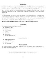
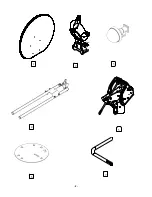
To avoid potential damage, the elliptical antenna should remain in its protective packaging until it is required. Pages one and 

two contain a list of package components. 


All the packaging is recyclable please dispose of it in a responsible manner. 


Summary of Contents for 98cm Elliptical Ku Antenna

Page 1: ...Instruction Manual for 98cm Elliptical Ku Antenna...

Page 2: ...r power lines is dangerous For your own safety follow these important safety rules 1 Perform as many functions as possible on the ground 2 Watch out for overhead power lines Check the distance to the...

Page 3: ...und telephone wires storm drains etc In addition because soils vary widely in composition and load capacity it may be necessary to consult a local professional engineer to determine the appropriate fo...

Page 4: ...LOS ADJUSTMENT 6 Key Components Reflector Box Number Description QTY 1 98cm Elliptical Reflector 1 Bracketry Box Number Description QTY 2 Antenna Back Bracket 1 3 Ku Feed Horn and Cap Assembly 1 4 Boo...

Page 5: ...iv 1 2 3 7 6 5 4...

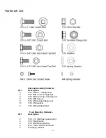
Page 6: ...carriage bolt 5 6 5 16 UNC x 3 4 hex head tap bolt 5 16 UNC hex nut 5 5 16 UNC serrated flange nut 10 5 16 UNC washer 6 5 16 UNC spring washer Feed Mounting Hardware QTY Description 2 2 5 16 x UNC he...

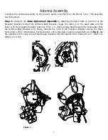
Page 7: ...Bracket Locate the letter A on the skew plate and the letter A on the elevation bracket Pass five 5 16 x 1 UNC Carriage Bolts through the skew plate then the Antenna Back Bracket and finally through t...

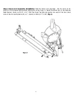
Page 8: ...s at the bottom of the Antenna Back Bracket aligning the screw holes To fasten the Boom arm to the Antenna Back Bracket insert one 5 16 x 3 4 UNC Hex Head Tap Bolt and washer into each of the four scr...

Page 9: ...3 Ku Feed Installation Attach the Feed Horn to the cradle using a 5 16 x UNC Hex Head Tap Bolt 5 16 flat washer 5 16 spring washer and 5 16 hex nut and tighten with a wrench to 20Nm 177 in lbf fig 3 F...

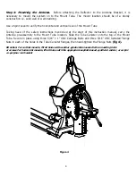
Page 10: ...of this instruction manual carry the Antenna pre assembly to the Mount Tube location Slide the Tube Canister onto the top of the Mount Tube Secure in place using three 5 16 x 1 UNC Carriage Bolts and...

Page 11: ...or locate the bolt and lower the reflector onto the antenna bracket by sliding the bolt down through the fork if the top tab on the antenna bracket Use the remaining 5 16 x UNC carriage bolts and thro...

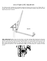
Page 12: ...ightly loosen the five 5 16 x 3 4 UNC Carriage Bolts fastening the Elevation Bracket to the Skew Plate through the Antenna Back Bracket It should not take pressure to move the dish the dish should mov...

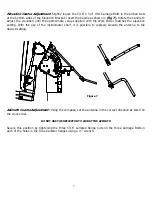
Page 13: ...der matches the elevation setting With the use of the inclinometer shelf it is possible to coarsely elevate the antenna to the desired setting Azimuth Coarse Adjustment Using the compass set the anten...

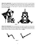
Page 14: ...the Azimuth Base to 20Nm 177 in lbf using a socket and Torque Wrench tightening opposing corners uniformly fig 8 Elevation Fine Adjustment Make final adjustments to the elevation by rotating the handl...

Reviews: