background image

Use and maintenance manual RBH 150 V - RBH 200 V

Pag.59 

Rev.2  15/07/2021

EN

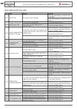
Stove phase general layout

Phase

Description


FINAL CLEANING

The stove is in the switch off phase and the cooling phase has not been completed 

yet

.

SWITCH ON

The heater pre-heating phase has started and the pellets start to fall into the grate.

WAITING FOR FLAME

The pellets ignite and take advantage of the heat in the intake air that passes through 

the incandescent heater tube.

FLAME PHASE

The flame develops in the grate

.

WORK AT MAX P

The stove has completed the switch on phase and runs at maximum set power

WORK AT MIN P

The stove works at the operating power set after ignition.

WORK AT DHW P 

The stove works at an operating capacity dedicated to DHW

(flow switch request with DHW kit or DHW boiler)

MODULATE H2O

The desired boiler water set temperature has been reached.

ROOM TEMPERATURE 

MODULATION

The room temperature set has been reached.

THE GRATE

Brazier cleaning phase is active (periodic function).

ECO STOP

With Climate Comfort active, the stove switches to automatic switch-off mode when 

the room temperature set is reached (see the dedicated section).

START/RESTART WAIT

Switch-on is requested but with the stove in cooling phase; once this condition is 

met, it restarts automatically.

SWITCH ON RESTART

The HOT restart phase is activated.

Functioning is similar to the SWITCH ON phase

HOT SMOKE

The maximum fume temperature threshold has been reached. To facilitate cooling, 

the stove brings the capacity to a minimum with ventilation at power level 5, leading 

to a decrease in fume temperature.

Summary of Contents for RBH 150 V

Page 1: ...EN DE ES NL Manuale d uso e manutenzione Manuel d utilisation et d entretien Use and maintenance manual Bedienungs und wartungshandbuch Manual de uso y mantenimiento Handleiding voor gebruik en onder...

Page 2: ...MANUALE D USO E MANUTENZIONE MANUEL D UTILISATION ET D ENTRETIEN RBH 150 V RBH 200 V...

Page 3: ......

Page 4: ...velli Modello Model Mod le RBH 150 V L oggetto della dichiarazione di cui sopra conforme alla pertinente normativa di armonizzazione dell Unione The object of the declaration described above is in con...

Page 5: ...zing Beachten Sie die Warnungen und Hinweise betreffend die Installation und regelm ige Wartung in der Bedienungsanleitung Respete las advertencias y las indicaciones de instalaci n y mantenimiento pe...

Page 6: ...zing Beachten Sie die Warnungen und Hinweise betreffend die Installation und regelm ige Wartung in der Bedienungsanleitung Respete las advertencias y las indicaciones de instalaci n y mantenimiento pe...

Page 7: ...cato T V Rheinland Energy GmbH NB 2456 ha determinato il prodotto tipo in base a prove di tipo secondo il sistema 3 ed ha rilasciato il rapporto di prova K27262019T1 8 Prestazioni dichiarate Specifica...

Page 8: ...Energy GmbH NB 2456 a d termin le produit type selon le syst me 3 et a d livr le rapport d essais K27262019T1 8 Prestations d clar e Sp cifications techniques harmonis es EN 14785 2006 Caract ristique...

Page 9: ...cato T V Rheinland Energy GmbH NB 2456 ha determinato il prodotto tipo in base a prove di tipo secondo il sistema 3 ed ha rilasciato il rapporto di prova K27262019T1 8 Prestazioni dichiarate Specifica...

Page 10: ...Energy GmbH NB 2456 a d termin le produit type selon le syst me 3 et a d livr le rapport d essais K27262019T1 8 Prestations d clar e Sp cifications techniques harmonis es EN 14785 2006 Caract ristique...

Page 11: ...rmio energetico a norma della Legge 10 91 e D P R 26 08 93 n 412 ammesse ad usufruire dei benefici fiscali connessi al contenimento dei consumi energetici negli edi fici ai sensi dell art 1 comma g de...

Page 12: ......

Page 13: ......

Page 14: ...non mettere da parte questo manuale senza averlo letto Installazioni scorrette manutenzioni non effettuate correttamente uso improprio del prodotto sollevano il Costruttore da ogni even tuale danno de...

Page 15: ...rincipali 27 Descrizione del funzionamento 27 Come estrarre il camino 28 Ricarica del combustibile 29 Formazione degli utenti 29 Dispositivi di sicurezza 30 TRASPORTO E INSTALLAZIONE 31 Avvertenze di...

Page 16: ...6 La modulazione 56 Eco stop 56 Stand by 56 Sanitario 56 Descrizione delle funzioni a menu 56 Impostazioni 60 Sistema anticondensa 61 Gestione ventilazione funzione presente solo per i modelli canaliz...

Page 17: ...e applicate le seguenti norme armonizzate e o specifiche tecniche EN 14785 EN 55014 1 EN 55014 2 EN 61000 3 2 EN 61000 3 3 EN 60335 1 EN 60335 2 102 EN 62233 EN 50581 ETSI EN 300220 1 Tutti i regolame...

Page 18: ...da materiali infiammabili Minimum distance from flammable materials Distance moindre de mat riels inflammables Distancia minima de materiales inflamables Minimale afstand van brandbare materialen Min...

Page 19: ...a verniciatura la griglia di combustione in acciaio inossidabile o in ghisa la resistenza le ceramiche le parti estetiche eventuali danni arrecati da una inadeguata installazione e o utilizzo del prod...

Page 20: ...zione Tecnica Simbologia utilizzata all interno del manuale simbolo definizione Simbolo utilizzato per identificare informazioni di particolare importanza all interno del manuale Le informazioni rigua...

Page 21: ...ili del Fuoco Utilizzare solo parti di ricambio originali Qualsiasi manomis sione e o sostituzione non autorizzata da Ravelli pu causare pericoli per l incolumit dell utente In caso di condizioni mete...

Page 22: ...ambiente Riscaldamento degli ambienti domestici mediante la combustione di Pellet di legno Qualsiasi altro combustibile diverso da quello consentito Domestico Commerciale La stufa progettata e costru...

Page 23: ...re effettuata da bambini senza sorveglianza non utilizzare la stufa in modo improprio cio per usi diversi da quelli indicati nel paragrafo USO PREVISTO tenere ad opportuna distanza di sicurezza il com...

Page 24: ...isce la norma EN PLUS definisce la qualit dei pellet definendo tre classi A1 A2 e B Il pellet deve essere trasportato ed immagazzinato in luogo asciutto Al contatto con l umidit si gonfia diventando q...

Page 25: ...200 2 200 Massima temperatura acqua impostabile C 75 75 Contenuto acqua L 17 17 Vaso di espansione L 6 6 Temperatura dei fumi C 89 140 96 173 Portata fumi g s 9 13 4 10 16 5 Tiraggio minimo Pa mbar 10...

Page 26: ...zione RBH 150 V RBH 200 V Pag 25 Rev 2 15 07 2021 IT Dimensioni Unit di misura RBH 150 V RBH 200 V Altezza mm 825 825 Larghezza mm 860 1000 Profondit mm 694 694 Peso a vuoto kg 185 190 Tavola tecnica...

Page 27: ...Manuale uso e manutenzione RBH 150 V RBH 200 V Pag 26 Rev 2 15 07 2021 IT Tavola tecnica RBH 200 V 732 777 76...

Page 28: ...arecchio controllato da una centralina elettronica che gestisce le fasi di accensione funzionamento e spegnimento e che inoltre include molte altre funzioni per il controllo per la programmazione e pe...

Page 29: ...o passo azione 1 Aprire la porta e azionare il meccanismo di sblocco facendo leva con l apposito attrezzo fornito a corredo manofredda come mostrato nel dettaglio 2 Tirare verso di s il camino 1 2 Rei...

Page 30: ...amino sia spento e completamente freddo Ricarica con kit di caricamento e o da apertura del rivestimento del camino Per caricare il pellet all interno del serbatoio procedere come descritto di seguito...

Page 31: ...nto elettrico dell abitazione sia a norma dotato di circuito di messa a terra e di tutti i sistemi di sicurezza previsti dalle norme Si segnala che il programma di funzionamento della stufa stato stud...

Page 32: ...de ogni altra operazione di montaggio o posa in opera Regolamenti amministrativi locali prescrizioni particolari delle autorit che riguardano l installazione di apparecchi a combustione la presa aria...

Page 33: ...ia collettiva Nella realizzazione della canna fumaria dovranno essere applicate le seguenti prescrizioni rispettare la norma di prodotto EN 1856 1 deve essere realizzata con materiali idonei per garan...

Page 34: ...ecchi di combustione o di impianto di VMC necessario verificare il corretto funzionamento dell apparecchio La stufa deve essere collocata all interno di ambienti abitativi La stufa non pu essere insta...

Page 35: ...ella stufa vedi Fig 2 Cenere depositata nella curva a 90 NO Presa d aria esterna Fig 2 In questo tipo di installazione Vedi Fig 3 il canale da fumo cio il tratto interno dell abitazione che collega la...

Page 36: ...i al tiraggio della stufa Vedi Fig 2 CANNA FUMARIA INTERNA Fig 5 Protezione dalla pioggia Lastra di copertura Lamiera in acciaio a tenuta stagna Raccordo a T con camera di raccolta e per condensa Boto...

Page 37: ...nferiore Entrata aria fredda 500 cm2 G Laterali in caso di installazione senza supporto 2 x 250 cm2 Distanze minime di sicurezza Distanze minime interne La nicchia di installazione deve essere realizz...

Page 38: ...rimuovere il camino dalla slitta se necessario staccare i tubi flessibili dalla slitta 3 Svitare e rimuovere la slitta dal supporto 4 Fissare la slitta al piano di appoggio 5 Estrarre le guide della s...

Page 39: ...anuale uso e manutenzione RBH 150 V RBH 200 V Pag 38 Rev 2 15 07 2021 IT Anche in questo tipo di installazione si deve prevedere la griglia di aerazione inferiore F oltre che quella superiore E 5 6 x4...

Page 40: ...rto procedere come descritto passo azione 1 Avvitare il supporto al pavimento 2 Regolare l altezza verticale del camino 1 La stufa dotata di un microinterruttore posto a lato del montante posteriore a...

Page 41: ...sezione H05RR F sez 3G0 75 Collegamento canna fumaria La canna fumaria deve essere dimensionata in modo tale da garantire il tiraggio dichiarato dal Costruttore La stufa deve essere collegata ad una c...

Page 42: ...ico automatico di blocco termostato a riarmo manuale Sistema di circolazione Sistema di espansione vaso di espansione Leggi e regolamenti locali ad esempio la norma UNI 10412 2 valida in Italia potreb...

Page 43: ...uito dal costruttore o il suo servizio assistenza tecnica o comunque da una persona con qualifica similare in modo da prevenire ogni rischio Interruttore Spina di ali mentazione Fusibile Collegamento...

Page 44: ...ne allarme uscita domotica TRF 58 S1 S2 S4 S5 S6 S3 G4 G7 G3 G2 M1 M2 M3 G5 nero rosso bianco M6 R1 C1 T2 T1 G1 nero rosso blu COM NC NO V2 V1 G5 G8 G3 G3 S6 S6 S4 S4 S3 S3 S1 S1 10 9 8 7 6 5 4 3 2 1...

Page 45: ...llegamenti per lo schema 0 solo riscaldamento S3 Collegamenti per lo schema 0 e Kit ACS Per utilizzare questo schema necessario il kit opzionale G3 S3 V1 V2 N Collegamenti per lo schema 1 boiler Per u...

Page 46: ...021 IT Collegamenti per lo schema 3 boiler puffer Per utilizzare questo schema necessario il kit opzionale S3 S1 S6 S4 Collegamenti per domotica e caldaia Per tutti gli schemi per utilizzare il contat...

Page 47: ...ietato collegare una valvola di intercettazione all uscita dello scarico di sicurezza L acqua in uscita dalla valvola di sicurezza potrebbe essere bollente Pericolo di ustione e di danni a cose e pers...

Page 48: ...dello schema idraulico da adottare deve essere fatta tramite il display al momento dell installazione della termostufa da parte di un tecnico autorizzato Schema 0 solo impianto di riscaldamento In que...

Page 49: ...iscaldamento Da questo momento la caldaia viene gestita dal termostato esterno o dal set H2O interno come per lo schema 0 La termostufa riscalda nuo vamente il Boiler quando la temperatura dell acqua...

Page 50: ...viene gestita dalla termostufa grazie ad una sonda La termostufa funziona alla potenza massima per raggiungere la temperatura del puffer impostata Quando viene raggiunta la stufa si porta in stato ECO...

Page 51: ...denza del caricamento dell impianto Tale accorgimento diventa indispensabile nelle condizioni sotto elencate durezza dell acqua media ed alta 15 f considerevoli quantit d acqua di reintegro o riempime...

Page 52: ...scegliere SI con i tasti di selezione e convalidare con il tasto di conferma Il display del palmare mostrer la seguente schermata Mantenere premuto per alcuni secondi il tasto di comunicazione radio R...

Page 53: ...terie nel palmare Togliere il coperchio di protezione delle batterie posto sul retro del telecomando come in figura A ed Inserire n 3 batterie tipo mini stilo AAA 1 5V nell alloggiamento del palmare f...

Page 54: ...essere caricato nel braciere e quindi poi la stufa si possa accendere Nel caso in cui non si eseguono le operazioni di carico coclea si potrebbero verificare episodi di mancata accensione della stufa...

Page 55: ...ficare il set temperatura acqua toccando il tasto freccia GI In tal modo questa parte del display viene evidenziata e viene mostrata la temperatura attualmente impostata Con i tasti freccia SU e frecc...

Page 56: ...eratura ACS toccando il tasto freccia SU In tal modo questa parte del display viene evidenziata e viene mostrata la temperatura attualmente impostata Con i tasti freccia SU e freccia GI possibile modi...

Page 57: ...circuito specialmente quando non attiva alcuna funzione di COMFORT CLIMA Se la stufa si trova in questa condizione passa automaticamente in STAND BY per garantire protezione al circuito idraulico La...

Page 58: ...crizione del funzionamento Impostazione potenza Queste stufe sono state progettate per regolare in automatico la potenza in base alla richiesta termica comunque possibile sce gliere di farla funzionar...

Page 59: ...la composizione anche sacchetti di pellet della stessa marca possono avere caratteristiche differenti In caso di combustione non ottimale variare il parametro del flusso per regolare l aria della comb...

Page 60: ...e il valore impostato sul palmare o sul termostato esterno la stufa attiva la fase di modulazione Se la temperatura raggiunta mantenuta per un periodo di tempo stabilito RITARDO SPEGNIMENTO la stufa s...

Page 61: ...pressione del tasto conferma per abilitare o disattivare la funzione Nella schermata Home al posto della temperatura ambiente rilevata ed impostabile compare la stringa T ON se la stanza in cui insta...

Page 62: ...il valore letto dalla sonda ambiente presente all interno del palmare aumentandolo o dimi nuendolo del valore impostato offset Effettuare tale regolazione con cautela e solo dopo aver verificato scost...

Page 63: ...o menu Per uscire dalla schermata e tornare alla schermata di Home premere ripetutamente il tasto Pressione del tasto di accesso a menu per accedere alla schermata MENU Pressione del tasto conferma pe...

Page 64: ...a di lavoro dedicata al sanitario richiesta del flussostato con KIT ACS o richiesta del Boiler ACS MODULA H2O E stato raggiunto il settaggio dell acqua caldaia desiderato MODULA AMBIENTE E stato raggi...

Page 65: ...et 5 prossima alla condizione di carico in continuo SOLUZIONE Portare il settaggio nuovamente a 0 ALLARME generico La termostufa si trova in stato di allarme consultare capitolo relativo agli allarmi...

Page 66: ...stufa Segnalazione Motivazione Risoluzione ESEGUIRE PULIZIA BRACIERE solo dove presente sistema RDS Lo sportello e il cassetto cenere non sono chiusi correttamente Verificare la loro corretta chiusura...

Page 67: ...one in fase di accensione inadeguata Rivolgersi al Servizio di Assistenza La resistenza per l accensione difettosa o non in posizione Rivolgersi al Servizio di Assistenza AL 06 PELLET ESAURITO Il serb...

Page 68: ...pres sione al valore richiesto per un corretto fun zionamento Se il problema persiste rivolgersi al Servizio Assistenza AL 17 NO FLUSSO solo dove presente si stema RDS Il debimetro non rileva un flus...

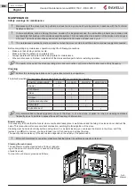
Page 69: ...nutenzione Pulizia Eseguire le operazioni di pulizia in modo da garantire il corretto funzionamento della stufa Nella seguente tabella vengono elencati gli interventi di pulizia necessari per il corre...

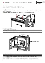
Page 70: ...minata l operazione di pulizia dello scambiatore spingere l asta dentro la griglia non lasciarlo mai estratto Pulizia della camera di combustione Per eseguire la pulizia della camera di combustione pr...

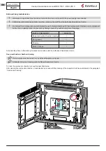
Page 71: ...dalla rottura improvvisa dei componenti PARTI FREQUENZA 1 STAGIONE Pulizia approfondita camera di combustione Guarnizione porta Canna fumaria Condotto fumi Programmare con il Centro di Assistenza Aut...

Page 72: ...Questa operazione deve essere svolta da un Centro Assistenza Ravelli Programmare con il Centro Assistenza Ravelli questo tipo di pulizia La stufa dotata di alcune botole per la pulizia dei condotti f...

Page 73: ...Manuale uso e manutenzione RBH 150 V RBH 200 V Pag 72 Rev 2 15 07 2021 IT 2 Botola Guarnizione Botola 3 Guarnizione Botola x6 x2...

Page 74: ...la scheda elettronica contattare il Servizio di Assistenza Tecnica AL 15 La fiamma non si accende Controllare che la candeletta scaldi Verifica ed eventuale sostituzione della can deletta AL 05 Condo...

Page 75: ...il condotto fumario AL 08 La porta non chiusa perfet tamente o le guarnizioni sono usurate Chiudere la porta e far sostituire le guarnizioni con altre originali AL 05 AL 06 La stufa si arresta automat...

Page 76: ...ica Sostituire batteria o collegamento alla stufa tramite cavo Telecomando guasto Sostituire telecomando La stufa funziona sempre alla massi ma potenza Temperatura non impostata correttamente Impostar...

Page 77: ...e che non ci siano altri apparecchi a combustione o cappe di aspirazione che mettano in depressione la stanza Accensione difficoltosa seguire attentamente quello che riportato nel capitolo dedicato di...

Page 78: ...ent ou la sant on invite l utilisateur s parer cet appareil et ou les piles ou les accumulateurs des autres types de d chets et de le confier au service municipal de collecte On peut demander au distr...

Page 79: ...lige stoffer indeholdt i produktet For at forebygge ventuelle skader for milj et eller sundheden bedes brugeren om at behandle dette udstyr og eller de medf lgende batterier eller akkumulatorerne sepa...

Page 80: ......

Page 81: ......

Page 82: ...ans un endroit appropri ne pas mettre ce manuel de c t sans l avoir lu Les installations incorrectes les entretiens effectu s incorrectement ainsi que l usage impropre du produit d gagent le Fabricant...

Page 83: ...Proc dure d extraction de l insert 96 Remplir le combustible 97 Formation des utilisateurs 97 Dispositifs de s curit 98 TRANSPORT ET INSTALLATION 99 Mises en garde de s curit pour le transport et l in...

Page 84: ...fonctions au menu 124 Programmation 128 Syst me anti condensation 129 Menu Ventilation fonction pr sente uniquement pour les mod les avec ventilation et canalisation 130 Sch ma synth tique phases du...

Page 85: ...techniques suivantes ont t appliqu es EN 14785 EN 55014 1 EN 55014 2 EN 61000 3 2 EN 61000 3 3 EN 60335 1 EN 60335 2 102 EN 62233 EN 50581 ETSI EN 300220 1 Toutes les r glementations locales y compris...

Page 86: ...anweisungen Distanza minima da materiali infiammabili Minimum distance from flammable materials Distance moindre de mat riels inflammables Distancia minima de materiales inflamables Minimale afstand v...

Page 87: ...a vitre de la porte les joints la peinture le panier combustion en acier inox ou en fonte la r sistance les majoliques en couleurs les pi ces esth tiques tout dommage caus par une installation et ou u...

Page 88: ...el symbole d finition Symbole utilis pour identifier des informations particuli rement importantes dans le manuel Les informations concernent aussi la s curit des utilisateurs concern s par l utilisat...

Page 89: ...s curit pourraient porter l arr t de la po le Dans tous les cas ne pas d sactiver les syst mes de s curit Pour le raccordement direct au r seau un dispositif doit tre pr vu pour assurer la d connexio...

Page 90: ...que ou commercial Le po le est con u et construit pour travailler en toute s curit si il est install en respectant les normes sp cifiques par un personnel qualifi il est employ dans les limites d clar...

Page 91: ...t strictement interdit d utiliser des combustibles liquides inflammables pour l allumage laisser les objets qui ne r sistent pas la chaleur et ou inflammables une distance de s curit opportune n alime...

Page 92: ...sation des granul s de bois certifi s classe A1 et A2 conform ment la norme EN ISO 17225 2 2014 ou certifi s DIN PLUS classe plus restrictive que la classe A1 ou ONORM M 7135 Les granul s qui peuvent...

Page 93: ...glable C 75 75 Contenu d eau L 17 17 Vase d expansion L 6 6 Temp rature des fum es C 89 140 96 173 D bit des fum es g s 9 13 4 10 16 5 Tirage minimum Pa mbar 10 0 1 10 0 1 Alimentation Hz V 50 230 50...

Page 94: ...mesure RBH 150 V RBH 200 V Hauteur mm 825 825 Largeur mm 860 1000 Profondeur mm 694 694 Poids vide kg 185 190 Sch ma technique RBH 150 V 733 777 76 48 AMEN E D AIR 100 SORTIE DES FUM ES 15 D CHARGE D...

Page 95: ...RBH 150 V RBH 200 V Pag 94 Rev 2 15 07 2021 FR Sch ma technique RBH 200 V 732 777 76 48 AMEN E D AIR 100 SORTIE DES FUM ES 15 D CHARGE DE S CURIT 3 4 RETOUR SYST ME 3 4 D PART SYST ME 15 D CHARGE DE L...

Page 96: ...uel Le po le est command par une unit de contr le lectronique qui g re les phases de d marrage de fonctionnement et d arr t et comprend galement de nombreuses autres fonctions de contr le de programma...

Page 97: ...la porte de la chemin et actionner le m canisme de d verrouillage en faisant levier sur l outil pr vu cet effet et fourni avec l appareil extracteur comme illustr dans le d tail ci dessous 2 Tirer l...

Page 98: ...ique que l accrochage a t effectu correctement Avant d extraire l insert et de charger le pellet veiller ce que l insert soit teint et compl tement froid Recharge avec kit de chargement et ou par l ou...

Page 99: ...t me lectrique de l habitation soit aux normes quip d un circuit de mise la terre et de tous les syst mes de s curit requis par les normes Il est noter que le programme de fonctionnement du po le a t...

Page 100: ...les prescriptions particuli res des autorit s qui concernent l installation d appareils combustion la prise d air et le dispositif d vacuation des fum es changent en fonction de la r gion ou du pays V...

Page 101: ...tie de toit il faut appliquer les prescriptions suivantes respecter la norme du produit EN 1856 1 il doit tre r alis avec des mat riaux appropri s pour garantir la r sistance aux contraintes m canique...

Page 102: ...combustion ou d un appareil de VMC il faut v rifier le fonctionnement correct de l appareil Le po le doit tre plac l int rieur de pi ces habitatives Il ne doit jamais tre install l ext rieur Le volume...

Page 103: ...a Fig 2 Cendres d pos es dans le coude 90 NON Prise d air l ext rieur IIl est possible d utiliser un conduit d vacuation des fum es existant ou une gaine technique au moyen d une canalisation Pour ce...

Page 104: ...dans la partie inf rieure du chaudi re ainsi qu l int rieur de la sortie de toit SORTIE DE TOIT INTERNE Fig 5 Protection de la pluie Plaque de recouvrement Lamiera in acciaio a tenuta stagna Raccord...

Page 105: ...inflammables ne peuvent tre plac s dans la zone surlign e dans le dessin Distances externes minimales C Lat ral 200 mm D Avant 800 mm Grille de ventilation Pour viter toute surchauffe de l appareil i...

Page 106: ...s crous et retirez l insert de la glissi re d tachez les tuyaux de la glissi re si n cessaire 3 D visser et retirer la glissi re du support 4 Fixer la glissi re la surface de support 5 Tirez les guide...

Page 107: ...el d utilisation et d entretien RBH 150 V RBH 200 V Pag 106 Rev 2 15 07 2021 FR Dans ce type d installation aussi il faut pr voir la grille d a ration inf rieure F en plus de la grille sup rieure E 5...

Page 108: ...l sur le support proc der comme d crit ci apr s tape action 1 Visser le support au sol 2 Ajustez la hauteur verticale de l insert Le po le est quip d un microrupteur situ sur le c t du montant post ri...

Page 109: ...n cas de remplacement est H05RR F sez 3G0 75 Raccordement la sortie de toit La sortie de toit doit tre dimensionn e de mani re assurer le tirage d clar par le Fabricant Le po le doit tre raccord une s...

Page 110: ...ique automatique de blocage thermostat r armement manuel Syst me de circulation Syst me d expansion vase d expansion Les lois et les r glementations locales par exemple la norme UNI 10412 2 valable en...

Page 111: ...tout cas par une personne ayant des qualifications similaires de mani re pr venir tout risque Interrupteur Fiche d ali mentation Fuse Connexion d une sonde externe ou d un thermostat Pour g rer le po...

Page 112: ...bianco M6 R1 C1 T2 T1 G1 nero rosso blu COM NC NO V2 V1 G5 G8 G3 G3 S6 S6 S4 S4 S3 S3 S1 S1 10 9 8 7 6 5 4 3 2 1 NC G8 NO G8 C G8 G7 G7 GND F N 1 2 V1 V2 20 19 18 17 16 15 14 13 12 11 Scheda OPZIONAL...

Page 113: ...ordement pour sch ma 0 uniquement installation de chauffage S3 Raccordement pour sch ma 0 et Kit ECS Le kit optionnel est n cessaire pour utiliser ce sch ma G3 S3 V1 V2 N Raccordement pour sch ma 1 ba...

Page 114: ...Raccordement pour sch ma 3 ballon ECS ballon tampon Le kit optionnel est n cessaire pour utiliser ce sch ma S3 S1 S6 S4 Raccordement pour domotique et chaudi re Pour tous les sch mas pour utiliser le...

Page 115: ...curit Il est interdit de raccorder une vanne d arr t la sortie de la vidange de s curit L eau sortant du clapet de s ret peut tre bouillante Risque de br lures et de dommages mat riels et corporels Le...

Page 116: ...ion de chauffage Dans ce type de circuit le po le est raccord directement l installation de chauffage C est le sch ma configur en s rie Ce sch ma est fourni titre indicatif et peut ne pas repr senter...

Page 117: ...le fluxostat si connect d tecte l utilisation d eau chaude sanitaire Si le thermopo le est en mode ECO STOP ou en mode STAND BY EAU aux conditions classiques de red marrage du sch ma 0 s ajoute la dem...

Page 118: ...escend sous cette valeur L avantage d utiliser le Puffer est qu il r gule le fonctionnement du thermo po le Le puffer peut tre raccord d autres unit s de production de chaleur telles que des panneaux...

Page 119: ...ment de l eau Le technicien responsable de l installation hydraulique est invit v rifier ce qui est indiqu dans les r glements en vigueur Charge d eau installation Lorsque les raccordements hydrauliqu...

Page 120: ...dinateur de poche Vert Cuisini re allum e E Touche d allumage d extinction de la cuisini re Pour tre en mesure de fonctionner correctement l ordinateur de poche n cessite une interface avec la carte l...

Page 121: ...atterie l arri re de la t l commande comme indiqu dans la figure A et entrez n 3 piles 1 5 V type AAA dans l emplacement de votre ordinateur en faisant attention la polarit Replacez le couvercle de pr...

Page 122: ...brasier et que le po le puisse ainsi ensuite s allumer Si les op rations de chargement de la vis sans fin ne sont pas effectu es il se peut qu il ait des pisodes de d faut d allumage du po le Apr s av...

Page 123: ...artie de l cran est mise en surbrillance et la temp rature actuellement configur e est affich e l aide des touches fl che vers le HAUT et fl che vers le BAS il est possible de modifier cette valeur La...

Page 124: ...cette fa on cette partie de l cran est mise en surbrillance et la temp rature actuellement configur e est affich e l aide des touches fl che vers le HAUT et fl che vers le BAS il est possible de modi...

Page 125: ...ger le circuit en particu lier quand aucune fonction COMFORT CLIMA n est active Si la chaudi re se trouve dans cette condition elle passe automatique ment en STAND BY pour garantir une protection au...

Page 126: ...nt la puissance en fonction de la demande thermique De toute fa on il est possible de choisir de le faire fonctionner la puissance minimale en utilisant cette fonction La s lection de la puissance n e...

Page 127: ...ranul s d une m me marque peuvent avoir des caract ristiques diff rentes En cas de combustion non optimale faites varier le param tre de d bit pour ajuster l air de combustion Si la seule r gulation d...

Page 128: ...la pi ce atteint la valeur configur e sur la t l commande tactile ou sur le thermostat externe le po le active la phase de modulation Si la temp rature atteinte est maintenue pendant une dur e d fini...

Page 129: ...d sactiver la fonction En tat de Home la place de la temp rature ambiante D tect e et configurable apparait la chaine T ON si la pi ce dans laquelle il est install le thermostat n a pas encore attein...

Page 130: ...inateur de poche en l augmentant ou en la diminuant de la valeur d finie offset Effectuez ce r glage avec prudence et seulement apr s avoir v rifi les carts par rapport la temp rature ambiante r elle...

Page 131: ...celle ci la configuration de MIN MAX Permet le choix de la vitesse de propagation de la chaleur Si configur la valeur AUTO la ventilation suit la puissance configur e du po le La temp rature lue au mo...

Page 132: ...aille une puissance de travail d di e au sanitaire demande du fluxostat avec KIT ACS ou demande du Chauffe eau ACS MODULE H2O Le r glage de l eau chaudi re voulu a t atteint MODULE ENVIRONMENT Le r gl...

Page 133: ...set pellets 5 est proche de la condition de charge en continu SOLUTION Ramenez le r glage de nouveau 0 ALARME g n rique Le po le se trouve dans un tat d alarme consulter chapitre sur les alarmes ANOM...

Page 134: ...extraordinaire du po le Indication Motivation Rasolution EXECUTER NETTOYAGE BRA SIER uniquement o pr sent Syst me RDS Le volet et le tiroir de cendre ne sont pas ferm s correctement V rifier la ferme...

Page 135: ...nt le charger Calibrage de la pastille et aspiration en phase d allumage erron S adresser au Service Assistance La r sistance l allumage est d fectueux ou hors position S adresser au Service Assistanc...

Page 136: ...tuer le remplissage de l installation ou l vent de ce dernier pour reporter la pression la valeur demand e pour un fonctionne ment correct Si le probl me persiste contactez votre Ser vice Assistance A...

Page 137: ...les op rations de nettoyage de mani re garantir le fonctionnement correct du po le Le tableau suivant num re les interventions de nettoyage n cessaires pour le fonctionnement correct du po le PI CE FR...

Page 138: ...nt et en arri re Une fois l op ration de nettoyage de l changeur termin e pousser le racleur l int rieur de la grille ne jamais le laisser sorti Nettoyage de la chambre de combustion Pour effectuer le...

Page 139: ...s composants PI CE FR QUENCE 1 SAISON Nettoyage en profondeur de la cham bre de combustion Joint de porte Sortie de toit Conduit de fum e Planifier avec le Centre de Service Autoris les op rations de...

Page 140: ...fum e Programmer ce type de nettoyage avec le Centre d assistance Ravelli Le po le est quip de quelques trappes pour le nettoyage des conduits de fum e internes Pour nettoyer les conduits de fum e pr...

Page 141: ...Manuel d utilisation et d entretien RBH 150 V RBH 200 V Pag 140 Rev 2 15 07 2021 FR 2 Joint Plaque d inspection 3 Plaque d inspection Joint Plaque d inspection x6 x2...

Page 142: ...lacer la carte lectronique contacter le service d assistance technique AL 15 La flamme ne s al lume pas Contr ler que la bougie d allu mage chauffe V rifier et le cas ch ant remplacer la bougie d allu...

Page 143: ...m e AL 08 La porte n est pas parfaitement ferm e ou les joints sont us s Fermer la porte et faire remplacer les joints par d autres d origine AL 05 AL 06 Le po le s arr te automatiquement Pr sence ala...

Page 144: ...g e Remplacer la pile ou la connexion au po le via c ble T l commande en panne Remplacer la t l commande Le po le fonctionne toujours la puis sance maximale La temp rature n est pas confi gur e correc...

Page 145: ...l n y ait pas d autres appareils combustion ou de hottes d aspiration qui mettent la pi ce en d pression Allumage difficile suivre attentivement les indications du chapitre d di de ce manuel contr ler...

Page 146: ...onnement ou la sant on invite l utilisateur s parer cet appareil et ou les piles ou les accumulateurs des autres types de d chets et de le confier au service municipal de collecte On peut demander au...

Page 147: ...e farlige stoffer indeholdt i produktet For at forebygge ventuelle skader for milj et eller sundheden bedes brugeren om at behandle dette udstyr og eller de medf lgende batterier eller akkumulatorerne...

Page 148: ......

Page 149: ...pour d ventuelles erreurs du pr sent opuscule et se retient libre de changer sans pr avis les caract ristiques de ses propres produits PNMU00047 IF Rev 2 15 07 2021 Aico S p A Headquarter Via Consorz...

Page 150: ...USE AND MAINTENANCE MANUAL RBH 150 V RBH 200 V...

Page 151: ......

Page 152: ...velli Modello Model Mod le RBH 150 V L oggetto della dichiarazione di cui sopra conforme alla pertinente normativa di armonizzazione dell Unione The object of the declaration described above is in con...

Page 153: ...zing Beachten Sie die Warnungen und Hinweise betreffend die Installation und regelm ige Wartung in der Bedienungsanleitung Respete las advertencias y las indicaciones de instalaci n y mantenimiento pe...

Page 154: ...zing Beachten Sie die Warnungen und Hinweise betreffend die Installation und regelm ige Wartung in der Bedienungsanleitung Respete las advertencias y las indicaciones de instalaci n y mantenimiento pe...

Page 155: ...monised standard The notified laboratory T V Rheinland Energy GmbH NB 2456 performed the determination of the product type on the basis of type testing under system 3 and issued test report K27262019T...

Page 156: ...monised standard The notified laboratory T V Rheinland Energy GmbH NB 2456 performed the determination of the product type on the basis of type testing under system 3 and issued test report K27262019T...

Page 157: ......

Page 158: ...do not discard it without reading it Incorrect installation maintenance and improper use of the product relieve the Manufacturer of all liability deriving from use of the stove For further informatio...

Page 159: ...agram RBH 150 V 21 Technical diagram RBH 200 V 22 Main parts 23 Description of operation 23 How to extract the fireplace 24 Recharge the fuel 25 User training 25 Safety devices 26 SHIPPING AND INSTALL...

Page 160: ...ases 52 Eco stop 52 Stand by 52 Sanitary 52 Description of menu functions 52 Setting 56 Anti condensation system 57 Ventilation menu function present only for ducted and ventilated models 58 Stove pha...

Page 161: ...ng harmonised standards and or technical specifications have been applied EN 14785 EN 55014 1 EN 55014 2 EN 61000 3 2 EN 61000 3 3 EN 60335 1 EN 60335 2 102 EN 62233 EN 50581 ETSI EN 300220 1 All loca...

Page 162: ...rom flammable materials Distance moindre de mat riels inflammables Distancia minima de materiales inflamables Minimale afstand van brandbare materialen Mindestabstand zu brennbaren Materialien 200 mm...

Page 163: ...or glass the gaskets the paint job the stainless steel or cast iron combustion grille the resistance the Majolica cladding the aesthetic parts any damages caused by unsuitable installation and or use...

Page 164: ...ified therefore if any inconsistency arises it will be necessary to follow the text in the original language or contact our Technical Documentation Office Symbols used in the manual symbol definition...

Page 165: ...igade Only use original spare parts Any tampering and or replacements that have not been authorised by Ravelli can pose a danger to the user s safety In the event of particularly adverse weather condi...

Page 166: ...red in the contract and herein the operating manual procedures are followed routine maintenance is carried out according to the times and methods set forth extraordinary maintenance is promptly carrie...

Page 167: ...stove to a regulation chimney provide a suitable system for the supply of combustion air air intake or intake duct for watertight stoves always perform maintenance with the stove off and cold perform...

Page 168: ...le distance Ravelli recommends using wood pellet classified A1 and A2 according to the EN ISO 17225 2 2014 standard or certified DIN PLUS more restrictive than the A1 class or ONORM M 7135 Pellet may...

Page 169: ...pressure bar kPa 2 200 2 200 Maximum adjustable water temperature C 75 75 Water content L 17 17 Expansion vessel L 6 6 Smoke temperature C 89 140 96 173 Smoke flow g s 9 13 4 10 16 5 Minimum draft Pa...

Page 170: ...rements Unit of measurement RBH 150 V RBH 200 V Height mm 825 825 Width mm 860 1000 Depth mm 694 694 Weight kg 185 190 Technical diagram RBH 150 V 733 777 76 48 AIR INLET 100 SMOKE OUTLET 3 4 FLOW 3 4...

Page 171: ...ce manual RBH 150 V RBH 200 V Pag 22 Rev 2 15 07 2021 EN Technical diagram RBH 200 V 732 777 76 48 AIR INLET 100 SMOKE OUTLET 3 4 FLOW 3 4 SYSTEM RETURN 15 SAFETY EXHAUST 694 EXTRACTION RUN 600MM 15 S...

Page 172: ...an electronic control unit that manages the start up operation and shutdown phases and also includes many other functions for control programming and safety The user can set the temperature to be mai...

Page 173: ...ow step 1 Open the door of the fireplace and activate the unlocking mechanism via leverage with the specific tool supplied extrac tor as shown in detail below 2 Pull the fireplace towards you Reinsert...

Page 174: ...acting the fireplace and loading the pellets make sure that the fireplace is off and completely cold Recharge with loading kit and or from the opening of the chimney cladding To load the pellets insid...

Page 175: ...l system of the house is up to standard equipped with a grounding circuit and all the safety systems required by the standards It should be noted that the stove s operating program has been designed t...

Page 176: ...ompatibility has a priority over any other assembly or installation operation Local administrative regulations and particular requirements of the authorities pertaining to the installation of combusti...

Page 177: ...ng the following regulations it must observe product standard EN 1856 1 it must be made of materials that are suitable to guarantee resistance against normal mechanical chemical and thermal stress and...

Page 178: ...tion in the presence of other combustion appliances or VMC system it is necessary to check the appliance for correct operation The stove must be placed inside living quarters It must never be installe...

Page 179: ...nstalled externally there is another one installed so that the outside section can be inspected It is prohibited to install two 90 bend since the ashes would quickly obstruct smoke passage causing dra...

Page 180: ...tial segment since the ashes would quickly obstruct smoke passage causing draught problems in the stove See Fig 2 INTERNAL CHIMNEY Fig 5 Protection from rain Covering sheet Air tight steel sheet metal...

Page 181: ...00 mm Minimum external distances Flammable objects and walls can not be placed within the high lighted area in the drawing Minimum external distances C Lateral 200 mm D Front 800 mm Air grills To avoi...

Page 182: ...fireplace from the slide detach the hoses from the slide if necessary 3 Unscrew and remove the slide from the support 4 Fix the slide to the support surface 5 Pull out the slide guides and place the...

Page 183: ...Use and maintenance manual RBH 150 V RBH 200 V Pag 34 Rev 2 15 07 2021 EN Also in this type of installation the lower ventilation grille F must be provided as well as the upper one E 5 6 x4...

Page 184: ...n the support proceed as follows step action 1 Screw the support to the floor 2 Adjust the vertical height of the fireplace The stove is supplied with a micro switch placed to the side of the rear jam...

Page 185: ...with relative section to be installed in case of replacement is H05RR F sez 3G0 75 Chimney connection The chimney must be sized so as to guarantee the draught declared by the Manufacturer The stove mu...

Page 186: ...the electronic board Automatic blocking thermal switch manual reset thermostat Circulation system Expansion system Expansion vessel Local laws and regulations for example the UNI 10412 2 standard val...

Page 187: ...commended that authorized personnel pay special attention to the electrical connections after any work on the product Switch Power plug Fuse Connection of external probe or thermostat To manage the st...

Page 188: ...3 G4 G7 G3 G2 M1 M2 M3 G5 nero rosso bianco M6 R1 C1 T2 T1 G1 nero rosso blu COM NC NO V2 V1 G5 G8 G3 G3 S6 S6 S4 S4 S3 S3 S1 S1 10 9 8 7 6 5 4 3 2 1 NC G8 NO G8 C G8 G7 G7 GND F N 1 2 V1 V2 20 19 18...

Page 189: ...iagrams Connections for diagram 0 heating system only S3 Connections for diagram 0 and DHW Kit The optional kit is required to use this diagram G3 S3 V1 V2 N Connections for diagram 1 boiler The optio...

Page 190: ...EN Connections for diagram 3 boiler buffer tank The optional kit is required to use this diagram S3 S1 S6 S4 Connections for home automation and gas boiler For all schemes to use the home automation...

Page 191: ...t is forbidden to connect a shut off valve to the safety drain outlet The water coming out of the safety valve could be hot Danger of burns and damage to people and things The manufacturer is not resp...

Page 192: ...m only In this type of circuit the stove is directly connected to the heating system This is the default set diagram The diagram shown here is indicative and may not display all the components require...

Page 193: ...ch if connected detects DHW being used If the thermo stove is in ECO STOP mode or in WATER STAND BY mode a request by the Boiler of flow meter is added to diagram 0 standard start up conditions The di...

Page 194: ...alls below this value The advantage of using a buffer tank is that it regulates the operation of the thermo stove The buffer tank can be connected to other heat production units such as solar panels a...

Page 195: ...y require the use of water softening systems The technician responsible for the plumbing installation is invited to check what is reported in the regulations in force System water load Once the plumbi...

Page 196: ...e in the menu Select the desired language with the scroll buttons and confirm your selection with the confirmation button In order to operate correctly the handheld set should be interfaced with the e...

Page 197: ...move the protective cover of the battery on the back of the remote control as shown in Figure A and insert the 3 batteries mini pen style battery AAA 1 5V in the housing of the handheld set and observ...

Page 198: ...After loading the auger and before lighting the stove always remember to empty the brazier and check that the brazier is clean Never empty the brazier inside the hopper After each maintenance operati...

Page 199: ...In this way this part of the display is highlighted and the currently set temperature is shown With the UP and DOWN arrow keys it is possible to modify this value The confirmation of each change take...

Page 200: ...is possible to change the DHW temperature set by touching the UP arrow key In this way this part of the display is highlighted and the currently set temperature is shown With the UP and DOWN arrow ke...

Page 201: ...t protecting the circuit especially when COMFORT CLIMATE function is not active on boiler H2O If the boiler is not in this condition it switches to STAND BY mode to guarantee protection of the hydraul...

Page 202: ...cription of operation Set power These stoves have been designed to automatically adjust the power according to the thermal demand However you can choose to run it at minimum power using this function...

Page 203: ...llets vary in grain size and composition even bags of pellets of the same brand can have different characteristics If combustion is not optimal vary the flow parameter to adjust the combustion air If...

Page 204: ...the palmtop or on the external thermostat the stove activates the modulation phase If the temperature reached is maintained for a set period of time DELAY SWITCH OFF the stove switches off automatica...

Page 205: ...confirm button to enable or disable the function In Home mode instead of room temperature measured and settable appears the line T ON if the room in which the thermostat is installed has not reached...

Page 206: ...lmtop increasing or decreasing it by the set value offset Make this adjustment carefully and only after having checked deviations from the actual room temperature with a reliable instrument Anti conde...

Page 207: ...MIN to MAX enables selecting the heat distribution speed If set to AUTO the ventilation follows the power set on the stove The temperature read by the handheld unit controls the modulation of the sto...

Page 208: ...ks at an operating capacity dedicated to DHW flow switch request with DHW kit or DHW boiler MODULATE H2O The desired boiler water set temperature has been reached ROOM TEMPERATURE MODULATION The room...

Page 209: ...llet setting set pellets 5 is near the continuous load condition SOLUTION Set the value back to 0 GENERIC ALARM The stove is in alarm state refer to the troubleshooting chapter ANOMALY general The sto...

Page 210: ...ne maintenance is required on the stove Signalling Reason Solution CLEAN THE GRATE only if the RDS sys tem is installed The door and the ash box are not closed correctly Make sure they are closed prop...

Page 211: ...n and suction during switch on phase is incorrect Contact the Support Service The ignition coil is faulty or positioned incorrectly Contact the Support Service AL 06 PELLETS FINISHED The pellet tank i...

Page 212: ...the value requested for correct operation If the problem persists contact the Support Service AL 17 NO FLOW only if the RDS system is installed The flow meter does not measure an input air flow Check...

Page 213: ...ng Perform the cleaning operations so as to guarantee correct stove operation The table below lists the necessary cleaning operations required for correct stove operation PARTS FREQUENCY 1 DAY 2 3 DAY...

Page 214: ...rod and firmly move the scraper back and forth Once you have finished cleaning the exchanger push the scraper inside the grill never leave it removed Combustion chamber cleaning To clean the ash drawe...

Page 215: ...etely broken to prevent any damage caused by sudden component breakage PARTS FREQUENCY 1 SEASON Deep combustion chamber cleaning Door gasket Chimney Smoke conduit Schedule the above extraordinary main...

Page 216: ...ration must be carried out by a Ravelli Assistance Centre Schedule this type of cleaning with the Ravelli Assistance Centre The stove is equipped with some hatches for cleaning the internal smoke duct...

Page 217: ...Use and maintenance manual RBH 150 V RBH 200 V Pag 68 Rev 2 15 07 2021 EN 2 Inspection hatch Gasket Inspection hatch 3 Gasket Inspection hatch x6 x2...

Page 218: ...ailed Replace the electronic board contact the Technical Assistance Service AL 15 The flame does not ignite Check that the igniter warms up Check and if necessary replace the igniter AL 05 Air inlet d...

Page 219: ...the smoke duct AL 08 The door is not closed perfectly or the gasket are worn Close the door and have the gaskets replaced with original ones AL 05 AL 06 The stove stops automatically Alarm presence C...

Page 220: ...l does not work Remote control battery low Replace battery or connection to the stove via cable Faulty remote control Replace remote control The stove always works at maximum power Temperature not set...

Page 221: ...n the room is clear of any obstructions and that there are no other combustion appliances or extraction hoods that create a vacuum in the room Difficult lighting closely follow the directions in the d...

Page 222: ...r s parer cet appareil et ou les piles ou les accumulateurs des autres types de d chets et de le confier au service municipal de collecte On peut demander au distributeur de pr lever le d chet d appar...

Page 223: ...r at forebygge ventuelle skader for milj et eller sundheden bedes brugeren om at behandle dette udstyr og eller de medf lgende batterier eller akkumulatorerne separat fra andre affaldstyper og at leve...

Page 224: ......

Page 225: ...free to make any variations to the features of its products without notice Aico S p A Headquarter Via Consorzio Agrario 3 D 25032 Chiari BS Italy Research and Development Centre Viale del commercio 1...

Page 226: ...BEDIENUNGS UND WARTUNGSHANDBUCH RBH 150 V RBH 200 V...

Page 227: ......

Page 228: ...Modelo Modelo RBH 150 V Het object van de bovengenoemde verklaring is on overeenstemming met de relevante harmonisatiewetgeving van de Unie Das vorhergehend erl uterte Produkt der Konformit tserkl ru...

Page 229: ...zing Beachten Sie die Warnungen und Hinweise betreffend die Installation und regelm ige Wartung in der Bedienungsanleitung Respete las advertencias y las indicaciones de instalaci n y mantenimiento pe...

Page 230: ...zing Beachten Sie die Warnungen und Hinweise betreffend die Installation und regelm ige Wartung in der Bedienungsanleitung Respete las advertencias y las indicaciones de instalaci n y mantenimiento pe...

Page 231: ...n Brandschutz Feuerbestandigkeit A1 Abstand von brennbarem Material Mindestabstand mm Ruckseite 50 Seite 200 Vorderseite 800 Himmel 50 Boden 0 Gefahr Brennstoffaustritt Konform Emission von Verbrennun...

Page 232: ...n Brandschutz Feuerbestandigkeit A1 Abstand von brennbarem Material Mindestabstand mm Ruckseite 50 Seite 200 Vorderseite 800 Himmel 50 Boden 0 Gefahr Brennstoffaustritt Konform Emission von Verbrennun...

Page 233: ......

Page 234: ...griffbereit auf Im Falle von fehlerhafter Installation und Wartung sowie unsachgem em Gebrauch des Produkts bernimmt der Hersteller keiner lei Verantwortung f r Sch den die durch die Verwendung des O...

Page 235: ...Hauptbauteile 23 Beschreibung der Operation 23 Anleitung zum Herausziehen des Kamins 24 Den Kraftstoff nachf llen 25 Einweisung des Benutzers 25 Sicherheitsvorkehrungen 26 TRANSPORT UND INSTALLATION 2...

Page 236: ...ie Modulation 52 Eco stop 52 Stand by 52 Warmwasser 52 Beschreibung der Men Funktionen 52 Antikondensation System 57 Management von Ventilation Funktion nur f r Modelle mit Ventilation und Canalisatio...

Page 237: ...onen wurden angewandt DE 14785 DE 55014 1 DE 55014 2 DE 61000 3 2 DE 61000 3 3 DE 60335 1 DE 60335 2 102 DE 62233 DE 50581 ETSI EN 300220 1 Bei der Installation des Ger ts m ssen alle rtlichen Vorschr...

Page 238: ...imum distance from flammable materials Distance moindre de mat riels inflammables Distancia minima de materiales inflamables Minimale afstand van brandbare materialen Mindestabstand zu brennbaren Mate...

Page 239: ...itter aus rostfreiem Stahl oder Gusseisen der Widerstand die Majolika die sthetischen Teile eventuelle Besch digungen infolge von fehlerhafter Installation und oder Verwendung des Produktes und oder N...

Page 240: ...estellt wird muss der Originaltext als Bezug verwendet werden bzw das technische Dokumentationsb ro des Herstellers kontaktiert werden Im Handbuch verwendete Symbole Symbol Definition Verwendetes Symb...

Page 241: ...ngen k nnten Sicherheitssysteme einschreiten die ein Abschalten der Heizung zur Folge haben Schalten Sie auf keinen Fall die Sicherheitssysteme ab F r den direkten Anschluss an das Stromnetz muss eine...

Page 242: ...ommerziell Ofen ist so entworfen und gebaut dass er sicher funktioniert wenn er nach den spezifischen Regeln von qualifiziertem Personal installiert wird innerhalb der im Vertrag und in diesem Handbuc...

Page 243: ...n verwendet werden vorausgesetzt dass sie berwacht werden der Ofen muss auf sachgem e Weise verwendet werdebn d h nur f r die im Abschnitt VORGESEHENER GEBRAUCH aufgef hrten Anwendungen es ist strikt...

Page 244: ...n 6 mm und eine L nge von 10 bis 40 mm Ihre Dichte betr gt ca 650 kg m3 Aufgrund des geringen Wassergehaltes 10 haben sie einen hohen Energiegehalt Die UNI EN ISO 17225 2 2014 die die Norm EN PLUS ers...

Page 245: ...0 2 200 Maximal einstellbare Temperatur C 75 75 Wassergehalt L 17 17 Ausgleichsbeh lter L 6 6 Temperatur der Rauchgase C 89 140 96 173 Rauchgasdurchsatz g s 9 13 4 10 16 5 Min Zug Pa mbar 10 0 1 10 0...

Page 246: ...a einheit RBH 150 V RBH 200 V H he mm 825 825 Breite mm 860 1000 Tiefe mm 694 694 Leergewicht kg 185 190 Technische Tafel RBH 150 V 733 777 76 48 LUFTEINTRITT 100 RAUCHGASAUSTRITT 3 4 PFLANZENLIEFERUN...

Page 247: ...BH 150 V RBH 200 V Pag 22 Rev 2 15 07 2021 DE Technische Tafel RBH 200 V 732 777 76 48 LUFTEINTRITT 100 RAUCHGASAUSTRITT 3 4 PFLANZENLIEFERUNG 3 4 RETURN PLANT 15 SICHERHEITSENTLADUNG 15 WASSERABLAUFS...

Page 248: ...nischen Steuereinheit gesteuert die Anlauf Betriebs und Abschaltphasen verwaltet und dar ber hinaus viele weitere Funktionen f r Steuerung Programmierung und Sicherheit umfasst Der Benutzer kann den S...

Page 249: ...ffnen und den Ausl semechanismus bet tigen indem man sie mit dem entsprechenden mitgeliefertem Werkzeug entnimmt K hler wie es hier unten detailliert visualisiert wird 2 Den Kamin zu sich ziehen Wied...

Page 250: ...vor der Kamin herausgezogen und das Pellet eingef llt wird sicherstellen dass der Kamin ausgeschaltet und kalt ist Nachf llen mit Nachf llbausatz und oder durch ffnen der Kaminverkleidung Um die Pelle...

Page 251: ...er bleibt Die Elektroanlage der Wohnung muss normkonform mit einem Erdungskreis und mit allen Sicherheitsvorkehrungen ausger s tet sein die vorgeschrieben sind Es wird darauf hingewiesen dass das Prog...

Page 252: ...tibilit tspr fung muss vor allen anderen Montage oder Installationsarbeiten ausgef hrt werden Lokale Verwaltungsvorschriften besondere Vorschriften der Beh rden bez glich der Installation von Verbrenn...

Page 253: ...Realisierung des Rauchfangs m ssen folgende Anforderungen erf llt werden Produktnorm EN 1856 1 er muss aus geeigneten Werkstoffen hergestellt sein um die Widerstandsf higkeit gegen normale mechanisch...

Page 254: ...et sein Bei einer Installation in der N he von anderen Verbrennungsger ten oder VMC Anlagen ist es notwendig den korrekten Betrieb des Ger ts zu berpr fen Der Ofen muss in einem Wohngeb ude ausgestell...

Page 255: ...liert werden F r den Schornstein ist es zwingend erforderlich ein isoliertes Rohr zu verwenden Im unteren Teil des Schornsteins wurde ein T Anschluss mit einer Inspektionskappe angebracht damit der u...

Page 256: ...inen horizontalen Abschnitt zur Verbindung mit einem vorhandenen Schornstein Beachten Sie die in der Abbildung gezeigten Steigungen um dieAscheablagerung im horizontalen Rohrabschnitt zu reduzieren Im...

Page 257: ...hervorgehobenen Bereichs d rfen sich keine brennbaren Gegenst nde und W nde befinden u ere Mindestabst nde C Seitlich 200 mm D Vorn 800 mm L ftungsgitter Um eine berhitzung des Einsatzes zu vermeiden...

Page 258: ...chlitten l sen Sie ggf die Schl uche vom Schlitten 3 Schrauben Sie den Schlitten von der Halterung ab und entfernen Sie ihn 4 Befestigen Sie den Schlitten an der Auflagefl che 5 Ziehen Sie die Gleitf...

Page 259: ...Bedienungs und Wartungshandbuch RBH 150 V RBH 200 V Pag 34 Rev 2 15 07 2021 DE Auch bei dieser Art der Installation muss das untere L ftungsgitter F sowie das obere E vorhanden sein 5 6 x4...

Page 260: ...n wie folgt Schritt Handlung 1 Schrauben Sie die Halterung an den Boden 2 Einstellen der vertikalen H he des Kamin Der Ofen ist mit einem Mikroschalter ausger stet der sich seitlich auf dem hinteren r...

Page 261: ...er im Falle eines Austauschs zu installieren ist H05RR F sez 3G0 75 Verbindung Rauchfang Der Rauchfang muss so dimensioniert sein dass der vom Hersteller angegebene Zug gew hrleistet ist Der Ofen muss...

Page 262: ...en Automatischer W rmeschutzschalter Thermostat mit manuellem Reset Kreislaufsystem Expansionssystem Ausdehnungsgef Lokale Gesetze und Verordnungen wie zum Beispiel die in Italien g ltige UNI 10412 2...

Page 263: ...hnlicher Qualifikation ersetzt werden um jegliches Risiko zu vermeiden Schalter Netzstecker Sicherung Anschluss von Temperaturf hler oder externem Thermostat Um den Ofen ber einen externen Thermostat...

Page 264: ...2 M3 G5 nero rosso bianco M6 R1 C1 T2 T1 G1 nero rosso blu COM NC NO V2 V1 G5 G8 G3 G3 S6 S6 S4 S4 S3 S3 S1 S1 10 9 8 7 6 5 4 3 2 1 NC G8 NO G8 C G8 G7 G7 GND F N 1 2 V1 V2 20 19 18 17 16 15 14 13 12...

Page 265: ...f r Schema 0 nur Heizanlage S3 Anschl sse f r Schema 0 und Brauchwasser KIT Das optionale Kit ist erforderlich um dieses Schema zu verwenden G3 S3 V1 V2 N Anschl sse f r Schema 1 Brauchwasserspeicher...

Page 266: ...Schema 3 Brauchwasserspeicher DHW Puffer Das optionale Kit ist erforderlich um dieses Schema zu verwenden S3 S1 S6 S4 Anschl sse f r Hausautomation und Kessel F r alle Schemata wird der Kontakt zur H...

Page 267: ...chluss eines Abfangventils am Ausgang des Sicherheitsauslasses ist verboten Das durch das Sicherheitsventil austretende Wasser kann kochend hei sein Verbrennungsgefahr und Gefahr von Sach und Personen...

Page 268: ...lage Bei dieser Art von Kreislauf ist der Ofen direkt mit der Heizanlage verbunden Dieses Schema ist serienm ig eingestellt Bei dem hier angegebenen Schema handelt es sich um Richtwerte und es sind ev...

Page 269: ...gswert sinkt oder wenn der Durchflussmesser falls angeschlossen die Verwendung von Brauchwasser erfasst Wenn sich der Heizofen entweder im Eco Stop Status oder im STAND BY Modus befindet kommen zu den...

Page 270: ...Temperatur des Puffers unter diesen Wert sinkt Der Vorteil der Verwendung des Puffers liegt darin dass er den Betrieb des Heizofen reguliert Der Puffer kann an andere w rme produzierende Ger te wie be...

Page 271: ...oder lokale Gesetze k nnen eventuell die Nutzung von Wasserenth rtungssystemen vorschreiben Der zust ndige Installationstechniker ist angehalten zu pr fen was die geltenden Verordnungen vorsehen Bef...

Page 272: ...ldung Sollte der PDA das erste Mal benutzt werden w hlen Sie JA mit den Auswahltasten und best tigen Sie mit der Best tigungstaste Das Display des PDAs zeigt nun folgenden Bildschirm Halten Sie die Ta...

Page 273: ...e Einlegen der Batterien in den PDA Entfernen Sie die Schutzabdeckung des Batteriefachs auf der R ckseite der Fernsteuerung wie in Abbildung A gezeigt und legen Sie 3 Batterien Typ AAA 1 5 V in das Ba...

Page 274: ...ens zum Laden in die Brennkammer bereit stehen und der Ofen angez ndet werden kann Wird die Schnecke nicht beladen kann es zu Fehlz ndungen des Ofens kommen Denken Sie nach dem Beladen der Schnecke un...

Page 275: ...iltaste ge ndert werden So wird dieser Teil des Displays hervor gehoben und die aktuell eingestellte Temperatur angezeigt Mit der oberen und unteren Pfeiltaste kann dieser Wert ver ndert werden Die Be...

Page 276: ...emperatur der Umgebung kann mit der oberen Pfeiltaste ge ndert werden So wird dieser Teil des Displays hervor gehoben und die aktuell eingestellte Temperatur angezeigt Mit der oberen und unteren Pfeil...

Page 277: ...sonders wenn keine KOMFORTKLIMA Funktion f r das Heizwasser aktiv ist Wenn die Heizung in dieser Kondition ist schaltet sie automatisch in STAND BY um den Schutz des Heizkreislaufs zu garantieren Die...

Page 278: ...Regelung Die fen sind so konzipiert dass ihre Leistung automatisch aufgrund des W rmebedarfs gesteuert wird Es ist trotzdem m glich den Ofen ber diese Funktion auf minimaler Leistung zu betreiben Die...

Page 279: ...tzung Selbst S cke mit Pellets derselben Marke k nnen unterschiedliche Eigenschaften aufweisen Bei nicht optimaler Verbrennung ist der Str mungsparameter zu variieren um die Verbrennungsluft einzustel...

Page 280: ...aktiviert der Ofen die Modulationsphase Wird die erreichte Temperatur f r eine eingestellte Zeitspanne beibehalten VERSPAETUNG OFF schaltet sich der Ofen automatisch aus und auf dem Display erscheint...

Page 281: ...oder zu deaktivieren Auf dem Bildschirm Home erscheint anstelle der erfassten und einstellbaren Raumtemperatur die Zeichenfolge T ON wenn der Raum in dem der Thermostat installiert ist die erforderlic...

Page 282: ...er ndert werden indem er um den eingestellten Wert Offset erh ht oder verringert wird F hren Sie diesen Abgleich mit Vorsicht und nur nach berpr fung der Abweichungen von der realen Raumtemperatur mit...

Page 283: ...ugreifen Bet tigung der Taste Best tigen um auf die Bildschirmseite BENUTZER zuzugreifen Bet tigung der Taste Best tigen um auf den Punkt L FTUNG berzugehen Zum Verlassen der Bildschirmseite und die R...

Page 284: ...it rwasser reservierten Betriebsleistung Anforderung des Durchflussmessers mit ACS KIT oder Anforderung des ACS Boi lers MODULA H2O Der gew nschte Wert f r die Heizwassertemperatur wurde erreicht MODU...

Page 285: ...nstellung der Pellets Einstellung Pellets 5 ist nahe an einer Kondition von ununterbrochener Zuf hrung L SUNG Setzen Sie den Wert erneut auf 0 WARNUNG allgemein Der Ofen befindet sich im Alarmzustand...

Page 286: ...anzufordern Meldung Ursache L sung FEUERSCHALE REINIGEN nur wenn ein RDS System vorhanden ist Die T r und der Aschenkasten sind nicht richtig geschlossen Pr fen Sie ob sie richtig geschlossen sind Sch...

Page 287: ...chf llen Kalibrierung der Pellets und der Luftzufuhr in der Z ndungsphase unzul nglich Wenden Sie sich an den Kundendienst Der Z ndwiderstand ist defekt oder falsch positioniert Wenden Sie sich an den...

Page 288: ...twa 1 0 bar F llen Sie den Kreislauf auf oder entl ften Sie ihn um den Druck auf den geforderten Wert f r ein korrektes Funktionieren zu bringen Wenn das Problem bestehen bleibt wenden Sie sich an den...

Page 289: ...hren dass der korrekte Betrieb des Ofens sichergestellt ist In der folgenden Tabelle werden die Reinigungseingriffe aufgef hrt die f r den korrekten Betrieb des Ofens erforderlich sind BAUTEILE FREQU...

Page 290: ...einer festen Bewegung vorw rts und r ckw rts Nach Beendigung der Reinigung des W rmetauschers den Schaber wieder in den Rost zur ckschieben er darf nicht in der herausgezo genen Position verbleiben Re...

Page 291: ...eventuelle Sch den durch pl tzlichen Bruch der Bauteile zu vermeiden BAUTEILE FREQUENZ 1 SAISON Gr ndliche Reinigung der Brennkammer Dichtung der T r Schornstein Schornstein Rauchabzug Planen Sie mit...

Page 292: ...elli Servicezentrum durchgef hrt werden Planen Sie diese Art der Reinigung mit dem Ravelli Service Centre Der Ofen ist mit einigen Luken zur Reinigung der internen Rauchkan le ausgestattet Zur Reinigu...

Page 293: ...Bedienungs und Wartungshandbuch RBH 150 V RBH 200 V Pag 68 Rev 2 15 07 2021 DE 2 Dichtung Inspektionsklappe 3 Inspektionsklappe Dichtung Inspektionsklappe x6 x2...

Page 294: ...taktieren St rung Triac Elektronikplatine austauschen technischen Kundendienst kontaktieren AL 15 Die Flamme geht nicht an berpr fen dass der Z nder sich erhitzt berpr fung und eventuell Ersatz des Z...

Page 295: ...ossen oder die Dichtungen sind abgenutzt T r schlie en bzw die Dichtungen mit ande ren Original Dichtungen ersetzen AL 05 AL 06 Der Ofen schaltet sich automatisch ab Ein Alarm liegt vor Alarm Tabelle...

Page 296: ...e der Fernbedienung leer Batterie austauschen oder Verbindung an Ofen ber Kabel Fernbedienung defekt Fernbedienung austauschen Der Ofen l uft st n dig auf maximaler Leistung Temperatur ist nicht korre...

Page 297: ...r Luftaustausch im Raum frei und ohne Hindernisse erfolgt und dass eine anderen Verbrennungsger te oder Absaughauben vorhanden sind die Unterdruck im Raum erzeugen Schwieriges Anz nden Aufmerksam die...

Page 298: ...r s parer cet appareil et ou les piles ou les accumulateurs des autres types de d chets et de le confier au service municipal de collecte On peut demander au distributeur de pr lever le d chet d appar...

Page 299: ...r at forebygge ventuelle skader for milj et eller sundheden bedes brugeren om at behandle dette udstyr og eller de medf lgende batterier eller akkumulatorerne separat fra andre affaldstyper og at leve...

Page 300: ......

Page 301: ...kte ohne Vorank ndigung zu ndern PNMU00047 DE Rev 2 15 07 2021 Aico S p A Headquarter Via Consorzio Agrario 3 D 25032 Chiari BS Italy Research and Development Centre Viale del commercio 12 a 37135 Ver...

Page 302: ...MANUAL DE USO Y MANTENIMIENTO RBH 150 V RBH 200 V...

Page 303: ......

Page 304: ...Modelo Modelo RBH 150 V Het object van de bovengenoemde verklaring is on overeenstemming met de relevante harmonisatiewetgeving van de Unie Das vorhergehend erl uterte Produkt der Konformit tserkl ru...

Page 305: ...zing Beachten Sie die Warnungen und Hinweise betreffend die Installation und regelm ige Wartung in der Bedienungsanleitung Respete las advertencias y las indicaciones de instalaci n y mantenimiento pe...

Page 306: ...zing Beachten Sie die Warnungen und Hinweise betreffend die Installation und regelm ige Wartung in der Bedienungsanleitung Respete las advertencias y las indicaciones de instalaci n y mantenimiento pe...

Page 307: ...8 Prestaciones declaradas Especificaci n t cnica armonizada EN 14785 2006 Caracter sticas esenciales Prestazione Sicurezza antincendio Resistencia al fuego A1 Distancia de materiales combustibles Dis...

Page 308: ...8 Prestaciones declaradas Especificaci n t cnica armonizada EN 14785 2006 Caracter sticas esenciales Prestazione Sicurezza antincendio Resistencia al fuego A1 Distancia de materiales combustibles Dis...

Page 309: ......

Page 310: ...id neo no lo guarde sin haberlo le do Las instalaciones incorrectas los mantenimientos no efectuados correctamente y el uso impropio del producto eximen al Fabrican te de cualquier da o que derive de...

Page 311: ...Tabla t cnica RBH 150 V 21 Tabla t cnica RBH 200 V 22 Componentes principales 23 Descripci n de la operaci n 23 C mo extraer el inserto 24 Vuelva a llenar el combustible 25 Formaci n de los usuarios 2...

Page 312: ...52 Descripci n de las funciones del men 52 Sistema anticondensacion 57 Gesti n de la ventilaci n funci n presente s lo en los modelos canalizados y ventilados 58 Esquema sint tico de las fases de la e...

Page 313: ...Y se han aplicado las siguientes normas armonizadas y o especificaciones t cnicas EN 14785 EN 55014 1 EN 55014 2 EN 61000 3 2 EN 61000 3 3 EN 60335 1 EN 60335 2 102 EN 62233 EN 50581 ETSI EN 300220 1...

Page 314: ...teriali infiammabili Minimum distance from flammable materials Distance moindre de mat riels inflammables Distancia minima de materiales inflamables Minimale afstand van brandbare materialen Mindestab...

Page 315: ...pintura la rejilla de combusti n de acero inoxidable o de fundici n la resistencia las may licas las partes est ticas las posibles aver as causadas por la instalaci n incorrecta y o uso del producto y...

Page 316: ...ar con nuestro Departamento de Documentaci n T cnica Simbolog a utilizada en el manual s mbolo definici n S mbolo utilizado para identificar informaciones de particular importancia en el manual Las in...

Page 317: ...e condiciones muy adversas podr an intervenir dispositivos de seguridad que causan el apagamiento de la estufa En cualquier caso no desactive los dispositivos de seguridad Para la conexi n directa a l...

Page 318: ...Cualquier otro combustible diferente del permitido Dom stica o comercial La estufa ha sido dise ada y fabricada para trabajar en seguridad si se instala siguiendo las normas espec ficas por personal c...

Page 319: ...manera impropia es decir para usos diferentes de los indicados en el apartado USO PREVISTO est prohibido terminantemente utilizar combustibles l quidos inflamables para el encendido mantenga a una dis...

Page 320: ...o de agua 10 tienen un alto contenido energ tico La norma UNI EN ISO 17225 2 2014 que sustituye a la norma EN PLUS define la calidad de los pellet y los diferencia en tres clases A1 A2 y B Mantenga lo...

Page 321: ...75 Cap c mara t rmica L 17 17 Vaso de expansi n L 6 6 Temperatura de humos C 89 140 96 173 Caudal de humos g s 9 13 4 10 16 5 Tiro m nimo Pa mbar 10 0 1 10 0 1 Alimentaci n Hz V 50 230 50 230 Consumo...

Page 322: ...idad de medida RBH 150 V RBH 200 V Altura mm 825 825 Ancho mm 860 1000 Profundidad mm 694 694 Peso en vac o kg 185 190 Tabla t cnica RBH 150 V 733 777 76 48 ENTRADA DE AIRE 100 SALIDA DE HUMOS 3 4 IMP...

Page 323: ...iento RBH 150 V RBH 200 V Pag 22 Rev 2 15 07 2021 ES Tabla t cnica RBH 200 V 732 777 76 48 ENTRADA DE AIRE 100 SALIDA DE HUMOS 3 4 IMPULSI N RETORNO 15 DESCARGA DE SEGURIDAD 15 SISTEMA DE DRENAJE DE A...

Page 324: ...al La estufa est controlada por una unidad de control electr nico que gestiona las fases de arranque funcionamiento y apagado y que tambi n incluye muchas otras funciones de control programaci n y seg...

Page 325: ...la puerta de la chimenea y accionar el mecanismo de desbloqueo haciendo palanca con la correspondiente herra mienta incluida extractor como se muestra en el detalle abajo 2 Tire del insert hacia usted...

Page 326: ...el insert y cargar el pellet aseg rese de que el insert est apagado y totalmente fr o Cargue usando el kit de carga y o la apertura del recubrimiento del insert Para cargar los pellets dentro de la t...

Page 327: ...la vivienda cumpla con la ley posea un circuito de puesta a tierra y todos los sistemas de seguridad exigidos por las normas Cabe se alar que el programa de funcionamiento de la estufa ha sido dise ad...

Page 328: ...o Los reglamentos administrativos locales las disposiciones especiales de las autoridades relativas a la instalaci n de aparatos de combusti n la toma de aire y el sistema de evacuaci n de humos puede...

Page 329: ...No conecte la estufa a un tubo de humos colectivo Al realizar el tubo de humos deber n aplicarse las disposiciones siguientes respete la norma de producto EN 1856 1 debe realizarse con materiales id...

Page 330: ...instalaci n en presencia de otros aparatos de combusti n o de instalaci n de VMC hay que comprobar el funcionamiento correcto del aparato La estufa debe colocarse dentro de ambientes habitacionales N...

Page 331: ...normas relativas a los sistemas de evacuaci n de humo en conductos En la parte inferior del tubo de humos ubicado dentro de la casa se ha instalado un conector tipo T con tapa de inspecci n en el exte...

Page 332: ...iempo el paso de los humos causando problemas en el tiro de la estufa Vea la Fig 2 Este tipo de instalaci n Vea la Fig 6 necesita un tramo horizontal para conectarse al tubo de humos ya existente Resp...

Page 333: ...o pueden colocarse objetos ni paredes inflamables dentro de la zona marcada en el dibujo Distancias m nimas externas C Lateral 200 mm D Delantera 800 mm Rejilla de ventilaci n Para evitar que la estuf...

Page 334: ...la chimenea de la corredera separe las mangueras de la corredera si es necesario 3 Desenroscar y retirar la corredera del soporte 4 Fijar la corredera a la superficie de apoyo 5 Saque las gu as de la...

Page 335: ...Manual de uso y mantenimiento RBH 150 V RBH 200 V Pag 34 Rev 2 15 07 2021 ES En este tipo de instalaci n tambi n se debe colocar una rejilla de ventilaci n inferior F as como una superior E 5 6 x4...

Page 336: ...orte proceda de la siguiente forma paso acci n 1 Atornille el soporte al suelo 2 Ajuste la altura vertical de la chimenea La estufa cuenta con un micro interruptor situado al lado del montante posteri...

Page 337: ...alado en caso de reemplazo es H05RR F sez 3G0 75 Conexi n a la chimenea La chimenea debe dimensionarse de manera que se garantice el calado declarado por el fabricante La estufa debe estar conectada a...

Page 338: ...rjeta electr nica Interruptor t rmico autom tico de bloqueo termostato con rearme manual Sistema de circulaci n Sistema de expansi n vaso de expansi n Las leyes y reglamentos locales por ejemplo la no...

Page 339: ...tencia t cnica o en todo caso por una persona con cualificaci n similar para evitar cualquier riesgo Interruptor Toma el ctrica Fusible Conexi n de la sonda externa o del termostato Para gestionar la...

Page 340: ...T1 G1 nero rosso blu COM NC NO V2 V1 G5 G8 G3 G3 S6 S6 S4 S4 S3 S3 S1 S1 10 9 8 7 6 5 4 3 2 1 NC G8 NO G8 C G8 G7 G7 GND F N 1 2 V1 V2 20 19 18 17 16 15 14 13 12 11 Scheda OPZIONALE per gestione schem...

Page 341: ...onexiones para esquema 0 solo instalaciones de calefacci n S3 Conexiones para esquema 0 y Kit de ACS Se requiere el kit opcional para usar este esquema G3 S3 V1 V2 N Conexiones para esquema 1 dep sito...

Page 342: ...onexiones para esquema 3 dep sito de ACS puffer Se requiere el kit opcional para usar este esquema S3 S1 S6 S4 Conexiones para dom tica y caldera Para todos los esquemas para utilizar el contacto de d...

Page 343: ...o conectar una v lvula de interceptaci n en la salida de la descarga de seguridad El agua que sale de la v lvula de seguridad puede estar muy caliente Peligro de quemaduras y da os a personas y cosas...

Page 344: ...ste tipo de circuito la estufa est conectada directamente a la instalaci n de calefacci n Es el esquema configurado de serie El esquema que se indica en este manual es indicativo y puede que no incluy...

Page 345: ...usa agua caliente sanitaria Si la termo estufa est en estado ECO STOP o en modalidad STAND BY AGUA con las condiciones cl sicas de puesta en marcha del esquema 0 se a ade la solicitud que proviene de...

Page 346: ...bajo de dicho valor La ventaja de usar el Puffer es que regula el funcionamiento de la termoestufa El puffer puede estar conectado a otras unidades para producir calor como por ejemplo a paneles solar...

Page 347: ...es y locales pueden imponer el uso de sistemas de ablandamiento del agua Se invita al t cnico responsable de la instalaci n hidr ulica a comprobar lo establecido en la normativa vigente Carga de agua...

Page 348: ...isponibles en el men Seleccione el idioma que se desea con las teclas de desplazamiento y convalide la selecci n con la tecla de confirmaci n Para funcionar correctamente la computadora necesita conec...

Page 349: ...a de protecci n de las bater as posterior como en la figura A e introduzca 3 bater as pila AAA 1 5V en el alojamiento de la computadora prestando atenci n a polaridades Vuelva a poner la tapa de prote...

Page 350: ...o para ser cargado en el brasero y por tanto se pueda encender la estufa En caso de que no se lleven a cabo las operaciones de carga del tornillo sin fin se podr an producir episodios de no encendido...

Page 351: ...anera esta parte de la pantalla se resalta y se muestra la temperatura configurada actualmente Con las teclas de flecha ARRIBA y flecha ABAJO es posible modificar este valor La confirmaci n de cualqui...

Page 352: ...parte de la pantalla se resalta y se muestra la temperatura configurada actualmente Con las teclas de flecha ARRIBA y flecha ABAJO es posible modificar este valor La confirmaci n de cualquier cambio s...

Page 353: ...funci n de CONFORT CLIMA en H2O caldera Si la caldera se encuen tra en esta condici n pasa autom ticamente en STAND BY para garantizar protecci n al circuito hidr ulico La caldera vuelve a arrancar au...

Page 354: ...laci n potencia Estas estufas han sido dise adas para regular autom ticamente la potencia en funci n de la demanda t rmica Sin embargo es posible elegir que funcione a la m nima potencia utilizando es...

Page 355: ...sici n incluso las bolsas de pellets de la misma marca pueden tener caracter sticas diferentes En caso de una combusti n no ptima variar el par metro de flujo para ajustar el aire de combusti n Si la...

Page 356: ...ambiente alcanza el valor configurado en el PDA o en el termostato externo la estufa activa la fase de modulaci n Si la temperatura alcanzada se mantiene durante un per odo de tiempo determinado ATRAS...

Page 357: ...bilitar la funci n En la pantalla de inicio en lugar de la temperatura ambiente detectada y ajustable aparece la cadena T ON si la habitaci n en la que est instalado el termostato no ha alcanzado a n...

Page 358: ...isminuy ndolo en el valor establecido offset Realice este ajuste con precauci n y s lo despu s de haber verificado las desviaciones de la temperatura real de la habita ci n con un instrumento fiable S...

Page 359: ...la estufa excluyendo cuando la llama pasa en modulaci n que tambi n el intercambiador se lleva de manera forzada al m nimo Presionar las teclas de aumento disminuci n para modificar la ventilaci n Fu...

Page 360: ...potencia dedicada al sanitario solicitud del interrup tor de flujo con KIT ACS o solicitud de la Caldera ACS M DULO H2O Se ha alcanzado la programaci n del agua de la caldera que se desea M DULO AMBIE...

Page 361: ...cerca de la condici n de carga continua SOLUCI N Poner de nuevo la configuraci n en 0 ALARMA gen rica La estufa se encuentra en un estado de alarma consulte el cap tulo relativo a las alarmas ANOMAL A...

Page 362: ...la termo estufa Indicaci n Motivaci n Soluci n REALIZAR LIMPIEZA DEL BRASERO solamente donde se encuentre presente el sistema RDS La portezuela y el caj n contenedor de ceniza no est n cerrados corre...

Page 363: ...CENDIDO FALLIDO El tanque del pellet est vac o Verificar la presencia de pellet en el tanque Eventualmente cargarlo Ajuste del pellet y de la aspiraci n en fase de encendido Ponerse en contacto con el...

Page 364: ...mienda con el circuito fr o una presi n de unos 1 0 bares Realice el llenado del sistema o el purgado del mismo para conducir la presi n al valor requerido para un correcto funcionamiento Si el probl...

Page 365: ...mpieza Realice las operaciones de limpieza para garantizar el funcionamiento correcto de la estufa En la tabla siguiente se indican las intervenciones de limpieza necesarias para que la estufa funcion...

Page 366: ...cia atr s Una vez terminada la operaci n de limpieza del intercambiador empuje el raspador hacia la rejilla nunca lo deje extra do Limpieza de la c mara de combusti n Para realizar la limpieza de la c...

Page 367: ...causados por la rotura repentina de los mismos PARTES FRECUENCIA 1 ESTACI N Limpieza minuciosa de la c mara de combusti n Junta de la puerta Chimenea Tubo de humos Programe con el centro de asistencia...

Page 368: ...da a cabo por un Centro de Servicio Ravelli Planifique este tipo de limpieza con el Centro de Servicio Ravelli La estufa est equipada con algunas escotillas para limpiar los conductos de humo internos...

Page 369: ...Manual de uso y mantenimiento RBH 150 V RBH 200 V Pag 68 Rev 2 15 07 2021 ES 2 Tapa de inspecci n Empaquetadura Tapa de inspecci n 3 Empaquetadura Tapa de inspecci n x6 x2...

Page 370: ...a Treenc fallo Sustituya la tarjeta electr nica contacte con el Servicio de Asistencia T cnica AL 15 La llama no se enciende Compruebe que la buj a se calienta Compruebe y si es necesario sustituya la...

Page 371: ...o de humos AL 08 La puerta no est perfecta mente cerrada o las juntas est n gastadas Cierre la puerta y sustituya las juntas por las originales AL 05 AL 06 La estufa se detiene autom ticamente Presenc...

Page 372: ...a descargada Sustituya la bater a o la conexi n a la estufa mediante cable Mando a distancia averiado Sustituya el mando a distancia La estufa siempre funciona a la m xi ma potencia La temperatura no...

Page 373: ...y que no haya otros aparatos de combusti n o campanas de aspiraci n que pongan la habitaci n en depresi n Encendido dificultoso siga atentamente lo que se indica en el cap tulo dedicado de este manua...

Page 374: ...r s parer cet appareil et ou les piles ou les accumulateurs des autres types de d chets et de le confier au service municipal de collecte On peut demander au distributeur de pr lever le d chet d appar...

Page 375: ...r at forebygge ventuelle skader for milj et eller sundheden bedes brugeren om at behandle dette udstyr og eller de medf lgende batterier eller akkumulatorerne separat fra andre affaldstyper og at leve...

Page 376: ......

Page 377: ...preaviso las caracter sticas de sus productos PNMU00047 ES Rev 2 15 07 2021 Aico S p A Headquarter Via Consorzio Agrario 3 D 25032 Chiari BS Italy Research and Development Centre Viale del commercio 1...

Page 378: ...HANDLEIDING VOOR GEBRUIK EN ONDERHOUD RBH 150 V RBH 200 V...

Page 379: ......

Page 380: ...Modelo Modelo RBH 150 V Het object van de bovengenoemde verklaring is on overeenstemming met de relevante harmonisatiewetgeving van de Unie Das vorhergehend erl uterte Produkt der Konformit tserkl ru...

Page 381: ...zing Beachten Sie die Warnungen und Hinweise betreffend die Installation und regelm ige Wartung in der Bedienungsanleitung Respete las advertencias y las indicaciones de instalaci n y mantenimiento pe...

Page 382: ...zing Beachten Sie die Warnungen und Hinweise betreffend die Installation und regelm ige Wartung in der Bedienungsanleitung Respete las advertencias y las indicaciones de instalaci n y mantenimiento pe...

Page 383: ...erstand tegen brand A1 Afstand van brandbaar materiaal Minimumafstand mm achterzijde 50 zijkant 200 voorzijde 800 plafond 50 onderzijde 0 Weerstand tegen brand Conform Uitstoot verbrandingsproducten 1...

Page 384: ...erstand tegen brand A1 Afstand van brandbaar materiaal Minimumafstand mm achterzijde 50 zijkant 200 voorzijde 800 plafond 50 onderzijde 0 Weerstand tegen brand Conform Uitstoot verbrandingsproducten 1...

Page 385: ......

Page 386: ...eze te hebben gelezen Onjuiste installatie niet goed uitgevoerd onderhoud oneigenlijk gebruik van het product ontheffen de Fabrikant van alle eventuele schade voortvloeiende uit het gebruik van de kac...

Page 387: ...dstoffen 19 TECHNISCHE KENMERKEN 20 Technische tekening RBH 150 V 21 Technische tekening RBH 200 V 22 Hoofdcomponenten 23 Beschrijving van de werking 23 Hoe de open haard te verwijderen 24 Bijvullen v...

Page 388: ...e statussen 51 OPERATIONELE FASEN VAN HET APPARAAT 52 Sequentie van de fasen van inschakeling 52 De modulatie 52 Eco stop 52 Stand by 52 Sanitair 52 Beschrijving van de menufuncties 52 Anti condens sy...

Page 389: ...ormen en of technische specificaties zijn toegepast EN 14785 EN 55014 1 EN 55014 2 EN 61000 3 2 EN 61000 3 3 EN 60335 1 EN 60335 2 102 EN 62233 EN 50581 ETSI EN 300220 1 Alle plaatselijke verordeninge...

Page 390: ...e lesen und befolgen Sie die Montage und Nutzungsanweisungen Distanza minima da materiali infiammabili Minimum distance from flammable materials Distance moindre de mat riels inflammables Distancia mi...

Page 391: ...n roestvrij staal of gietijzer de weerstand de keramische delen de esthetische delen eventuele schade veroorzaakt door een verkeerde installatie en of gebruik van het product en of nalatigheid van de...

Page 392: ...rspronkelijke taal worden gevolgd of moet u contact opnemen met onze Afdeling Technische Documentatie Gebruikte symbolen in de handleiding symbool definitie Symbool gebruikt om informatie van bijzonde...

Page 393: ...ruiker veroorzaken Bij bijzonder slechte weersomstandigheden kunnen de veiligheidssystemen ingrijpen door de kachel uit te schakelen Schakel nooit de veiligheidssystemen uit Voor een directe verbindin...

Page 394: ...dstof Woning Commercieel De kachel is ontworpen en gebouwd om veilig te werken als deze wordt ge nstalleerd volgens de specifieke voorschriften door gekwalificeerd personeel deze wordt gebruikt binnen...

Page 395: ...worden verricht en mag niet door kinderen zonder toezicht worden uitgevoerd niet de kachel op oneigenlijke wijze gebruiken dat wil zeggen voor ander gebruik dan aangegeven in de paragraaf BEOOGD GEBRU...

Page 396: ...getisch gehalte De norm UNI EN ISO 17225 2 2014 die het ENplus label vervangt bepaalt de kwaliteit van de pellets met een indeling in drie klassen A1 A2 en B De pellets moeten worden vervoerd en opges...

Page 397: ...ar kPa 2 200 2 200 Maximaal instelbare watertemperatuur C 75 75 Waterinhoud L 17 17 Expansievat L 6 6 Temperatuur van de rookgassen C 89 140 96 173 Debiet rookgassen g s 9 13 4 10 16 5 Minimum trek Pa...

Page 398: ...Afmetingen Meeteenheid RBH 150 V RBH 200 V Hoogte mm 825 825 Breedte mm 860 1000 Diepte mm 694 694 Leeggewicht kg 185 190 Technische tekening RBH 150 V 733 777 76 48 AIR INLET 100 SMOKE OUTLET 3 4 FLO...

Page 399: ...en onderhoud RBH 150 V RBH 200 V Pag 22 Rev 2 15 07 2021 NL Technische tekening RBH 200 V 732 777 76 48 AIR INLET 100 SMOKE OUTLET 3 4 FLOW 3 4 SYSTEM RETURN 15 SAFETY EXHAUST 694 EXTRACTION RUN 600M...

Page 400: ...eleenheid die de fasen van inschakeling werking en uitschakeling beheert en die tevens vele andere functies voor de controle de programmering en de veiligheid bevat De gebruiker kan de temperatuur ins...

Page 401: ...ctie 1 Open de deur en bedien het ontgrendelingsmechanisme door het omhoog te duwen met het speciale meegeleverde gereedschap koeler zoals in detail weergegeven 2 Trek de open haard naar u toe Terugpl...

Page 402: ...ns de open haard te verwijderen en de pellet te laden overtuig u ervan dat de open haard uit en volledig afgekoeld is Vullen met vulkit en of via de opening van de coating van de open haard Voor het l...

Page 403: ...eilig Het is noodzakelijk dat de elektrische installatie van de woning voldoet aan de normen voorzien is van een aardingscircuit en van alle door de normen vereiste veiligheidssystemen Opgemerkt wordt...

Page 404: ...gaat vooraf aan elke andere montage of installatiehandeling Plaatselijke administratieve verordeningen bijzondere voorschriften van de gezaghebbende instanties met betrekking tot de installatie van v...

Page 405: ...de verwezenlijking van het rookafvoerkanaal moeten de volgende voorschriften worden toegepast het moet voldoen aan de productnorm EN 1856 1 het moet gemaakt worden van geschikte materialen om weerstan...

Page 406: ...ingstoestellen of van een installatie met mechanische ventilatie moet de correcte werking van het apparaat gecontroleerd worden De kachel moet binnenshuis in leefomgevingen worden geplaatst De kachel...

Page 407: ...veroorzaakt zie afb 2 Afgezette as in de bocht van 90 NEE Externe luchtinlaat Afb 2 Bij dit type installatie zie afb 3 vereist het rookkanaal dat wil zeggen het interne trac van de woning dat de kach...

Page 408: ...en zo trekproblemen van de kachel veroorzaakt zie afb 2 INTERN ROOKAFVOERKANAAL Afb 5 Bescherming tegen de regen Afdekplaat Lekdichte staalplaat T koppeling met opvang kamer en voor condens Inspectie...

Page 409: ...randbare voorwerpen en wanden binnen het in de tekening gemarkeerde gebied zijn Minimum externe afstanden C Zijkant 200 mm D Voorkant 800 mm Ventilatieroosters Om oververhitting van het toestel te ver...

Page 410: ...en los en verwijder de open haard van de slede maak indien nodig de slangen los van de slede 3 Schroef de slede los en verwijder hem van de steun 4 Bevestig de slede op het steunvlak 5 Trek de geleide...

Page 411: ...eiding voor gebruik en onderhoud RBH 150 V RBH 200 V Pag 34 Rev 2 15 07 2021 NL Ook in dit type installatie moet gezorgd worden voor een luchtrooster aan de onderkant F naast die aan de bovenkant E 5...

Page 412: ...alleren gaat u als volgt te werk stap actie 1 Schroef de steun aan de vloer 2 Stel de verticale hoogte van de open haard in De kachel is voorzien van een microschakelaar aan de kant van de rechter ach...

Page 413: ...emonteerd is H05RR F doorsn 3G0 75 Aansluiting rookafvoerkanaal Het rookafvoerkanaal moet van zodanige afmeting zijn dat de door de Fabrikant verklaarde trek wordt gegarandeerd De kachel moet worden a...

Page 414: ...lokkeerschakelaar thermostaat met handmatige reset Circulatiesysteem Expansiesysteem expansievat Lees de plaatselijke voorschriften bijvoorbeeld de norm UNI 10412 2 van kracht in Itali deze schrijven...

Page 415: ...centrum of in elk geval door iemand met een gelijkwaardige kwalificatie teneinde elk risico te voorkomen Schakelaar Voedingsstekker Zekering Aansluiting externe sonde of thermostaat Om de kachel te be...

Page 416: ...G3 G2 M1 M2 M3 G5 nero rosso bianco M6 R1 C1 T2 T1 G1 nero rosso blu COM NC NO V2 V1 G5 G8 G3 G3 S6 S6 S4 S4 S3 S3 S1 S1 10 9 8 7 6 5 4 3 2 1 NC G8 NO G8 C G8 G7 G7 GND F N 1 2 V1 V2 20 19 18 17 16 15...

Page 417: ...ema s Aansluitingen voor schema 0 alleen verwarmingssysteem S3 Aansluitingen voor schema 0 en SWW Kit De optionele kit is vereist om dit schema te gebruiken G3 S3 V1 V2 N Aansluitingen voor schema 1 S...

Page 418: ...1 NL Aansluitingen voor schema 3 SWW tank buffer De optionele kit is vereist om dit schema te gebruiken S3 S1 S6 S4 Aansluitingen voor huisautomatisering en ketel Voor alle schema s is het huisautomat...

Page 419: ...en een afsluitklep op de uitgang van de veiligheidsafvoer aan te sluiten Het water dat uit de veiligheidsklep naar buiten komt kan kokend heet zijn Gevaar voor brandwonden en schade aan zaken en perso...

Page 420: ...rkende technicus Schema 0 alleen verwarmingssysteem In dit type circuit wordt de kachel direct op het verwarmingssysteem aangesloten Standaard is dit schema ingesteld Het hier afgedrukte schema is ind...

Page 421: ...t of wanneer de debietschakelaar indien aangesloten het gebruik van sanitair warm water detecteert Als de thermokachel in de status ECO STOP of in modus STAND BY WATER is onder de gebruikelijke hersta...

Page 422: ...STOP en herstart automatisch als de temperatuur van de buffer onder die waarde daalt Het voordeel van het gebruik van de buffer is dat deze de werking van de thermokachel regelt De buffer kan op ande...

Page 423: ...ekere complexheid en afmeting Nationale en plaatselijke wetten kunnen het gebruik van wateronthardingssystemen opleggen De verantwoordelijke installateur van het hydraulisch systeem moet verifi ren wa...

Page 424: ...estigingstoets Om correct te kunnen werken moet de handset in verbinding zijn met de elektronische kaart die zich in de kachel bevindt Om deze reden wordt op het display het volgende bericht getoond W...

Page 425: ...laatsen Verwijder het beschermpaneel van de batterijen dat zich op de achterkant van de afstandsbediening bevindt zie afbeelding A en plaats 3 batterijen type potlood AAA 1 5V in het compartiment van...

Page 426: ...e kachel vervolgens ingeschakeld kan worden Als de toevoerschroef niet wordt geladen kan het gebeuren dat de kachel niet aangaat Wanneer de toevoerschroef is geladen en voordat u de kachel inschakelt...

Page 427: ...te wijzigen door op de pijltoets OMLAAG te drukken Op deze manier wordt dit deel van het display gemarkeerd en wordt de op dat moment ingestelde temperatuur getoond Met de pijltoetsen OMHOOG en OMLAAG...

Page 428: ...mperatuur te wijzigen door op de pijltoets OMHOOG te drukken Op deze manier wordt dit deel van het display gemarkeerd en wordt de op dat moment ingestelde temperatuur getoond Met de pijltoetsen OMHOOG...

Page 429: ...nneer er geen KLIMAAT COMFORT functie actief is Als de kachel zich in deze toestand bevindt dan gaat hij automatisch in STAND BY om bescherming te garanderen aan het hydraulisch circuit De ketel herst...

Page 430: ...hels zijn ontworpen om automatisch het vermogen te regelen op basis van de warmte aanvraag Het is hoe dan ook moge lijk om via deze functie te kiezen de kachel op minimum vermogen te laten werken De s...

Page 431: ...etzelfde merk kunnen verschillende kenmerken hebben Wanneer de verbranding niet optimaal is kunt u de parameter van de luchtstroom veranderen om de lucht van de verbranding aan te passen Als de aanpas...

Page 432: ...op de externe thermostaat bereikt activeert de kachel de modulatiefase Als de bereikte temperatuur wordt gehandhaafd gedurende een vastgestelde tijdsperiode VERTRAGING UITSCHAKELING gaat de kachel aut...

Page 433: ...ukt kunt u de functie in of uitschakelen Op het beginscherm verschijnt in de plaats van de waargenomen en instelbare omgevingstemperatuur de melding T ON als de kamer waarin de thermostaat is ge nstal...

Page 434: ...aanwezige omgevingssonde wijzigen door deze te verhogen of te verlagen ten opzichte van de ingestelde waarde offset Voer een dergelijke aanpassing voorzichtig uit en pas nadat u afwijkingen hebt geco...

Page 435: ...an MIN tot MAX kan de verspreidingssnelheid van de warmte worden gekozen Als de waarde AUTO wordt gekozen volgt de ventilatie het geconfigureerde vermogen van de kachel Als de AUTO functie niet is ing...

Page 436: ...rmogen speciaal voor het sanitair aanvraag van de debietschakelaar met SWW KIT of aanvraag van de SWW tank MODULE H2O De gewenste instelling van het ketelwater is bereikt MODULE OMGEVING De gewenste i...

Page 437: ...pellets set pellets 5 dichtbij permanent laden is OPLOSSING Plaats de afstelling opnieuw op 0 ALARM algemeen De kachel bevindt zich in een alarmstand raadpleeg het hoofdstuk over alarmen AFWIJKING al...

Page 438: ...on onderhoud voor de thermokachel aan te vragen Melding Reden Oplossing VUURPOT REINI GING UITVOEREN alleen waar het RDS systeem aan wezig is Het deurtje en de aslade zijn niet goed gesloten Controlee...

Page 439: ...zuiging in de ontstekingsfase Richt u tot de Klantendienst De ontstekingsweerstand is defect of zit niet op zijn plaats Richt u tot de Klantendienst AL 06 GEEN PELLETS MEER Het pelletreservoir is leeg...

Page 440: ...systeem om de druk op de waarde te bren gen die vereist is voor een correcte werking Neem contact op met de klantendienst als het probleem aanhoudt AL 17 GEEN LUCHT STROOM alleen waar het RDS systeem...

Page 441: ...dsinterventies be nvloeden Reiniging Voer de reinigingswerkzaamheden uit zodat een correcte werking van de kachel kan worden gegarandeerd In de volgende tabel worden de reinigingsinterventies opgesomd...

Page 442: ...het schraapijzer met een krachtige beweging heen en weer Is de reiniging van de warmtewisselaar eenmaal voltooid duw de schraper dan in het rooster laat het nooit naar buiten getrokken Reiniging van d...

Page 443: ...chade veroorzaakt door een plotselinge breuk van de componenten te voorkomen ONDERDELEN FREQUENTIE 1 SEIZOEN Grondige reiniging van de verbran dingskamer Pakking deur Rookafvoerkanaal Rookgaskanaal Pl...

Page 444: ...ze handeling moet worden uitgevoerd door een Servicecentrum van Ravelli Plan dit soort reiniging met het Servicecentrum van Ravelli De kachel is uitgerust met een aantal luiken voor de reiniging van d...

Page 445: ...Handleiding voor gebruik en onderhoud RBH 150 V RBH 200 V Pag 68 Rev 2 15 07 2021 NL 2 Dichtin Inspectieplaat 3 Inspectieplaat Dichtin Inspectieplaat x6 x2...

Page 446: ...de elektronische kaart neem contact op met de Technische Assistentiedienst AL 15 De vlam gaat niet branden Controleer of de ontstekings bougie verwarmt Verifieer en vervang de ontstekingsbougie zo nod...

Page 447: ...deur is niet perfect gesloten of de pakkingen zijn versleten Sluit de deur en laat de pakkingen vervangen door nieuwe originele exemplaren AL 05 AL 06 De kachel stopt automatisch Aanwezigheid alarm Co...

Page 448: ...an de afstandsbe diening is leeg Vervang de batterij of de aansluiting op de kachel met kabel De afstandsbediening is defect Vervang de afstandsbediening De kachel werkt al tijd op het maximum vermoge...

Page 449: ...an belemmeringen en of er geen andere verbrandingstoestellen of afzuigkappen zijn die de ruimte in onderdruk brengen Moeizame ontsteking volg nauwkeurig hetgeen is vermeld in het desbetreffende hoofds...

Page 450: ...r s parer cet appareil et ou les piles ou les accumulateurs des autres types de d chets et de le confier au service municipal de collecte On peut demander au distributeur de pr lever le d chet d appar...

Page 451: ...r at forebygge ventuelle skader for milj et eller sundheden bedes brugeren om at behandle dette udstyr og eller de medf lgende batterier eller akkumulatorerne separat fra andre affaldstyper og at leve...

Page 452: ......
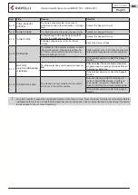
Page 453: ...eving wijzigingen aan te brengen in de kenmerken van de eigen producten PNMU00047 NL Herz 2 15 07 2021 Aico S p A Headquarter Via Consorzio Agrario 3 D 25032 Chiari BS Italy Research and Development C...

Reviews: