EN
Page 20 of 91
INSTRUCTION, USE AND
MAINTENANCE MANUAL
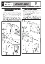
4. Connect connector (
Fig. 17 ref. 1
) of the cable
coming from inside the machine to connector
(
Fig. 17 ref. 2
) of the cable coming from the gauge
arm. Fit the section of the cable with the connectors
inside the arm (
Fig. 17 ref. 3
).
5. Fasten the cable with clamps.
6. Enable the external data gauge and carry out the
device calibration.
Fig. 17
9.2.5 Fitting the protection guard
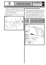
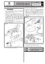
1. Mount the protection guard (
Fig. 18 ref. 1
) to the
support (
Fig. 18 ref. 2
) using the screws (
Fig. 18
ref. 3
), interposing the Belleville washers (
Fig. 18
ref. 4
) and the tab washers (
Fig. 18 ref. 5 - 6
).
2. Tighten the screws (
Fig. 18 ref. 3
) in order to
make the guard (
Fig. 18 ref. 1
) lift or lower with-
out bumping against the limit switch. Carry out the
adjustment so that it's possible to manually guide
the guard both during closing and opening.
DURING GUARD ASSEMBLY,
PAY ATTENTION TO THE MICRO
PLACED INSIDE THE MACHINE.
Fig. 18
G3.150 - GP3.150 - G3.150S - GP3.150S - G3.150WS - GP3.150WS - G3.150WSPLUS - GP3.150WSPLUS - G3.150SA - G3.150WSA
RAVAGLIOLI S.p.A.
1297-M058-00

